
Land Rover Defender: Engine
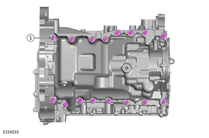
Engine - Ingenium I4 2.0l Petrol/Ingenium I4 2.0l Petrol - PHEV
SPECIFICATIONS
Lubricants, Fluids, Sealers and Adhesives
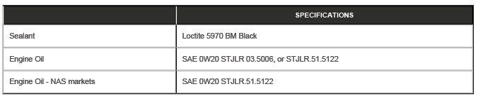
Capacities
.png)
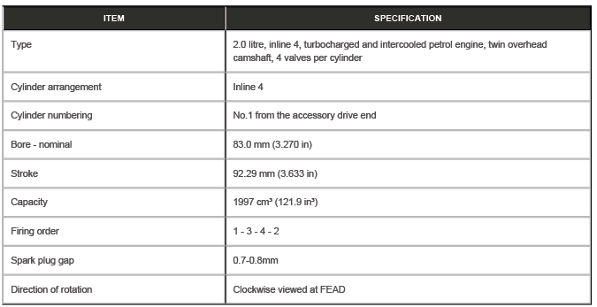
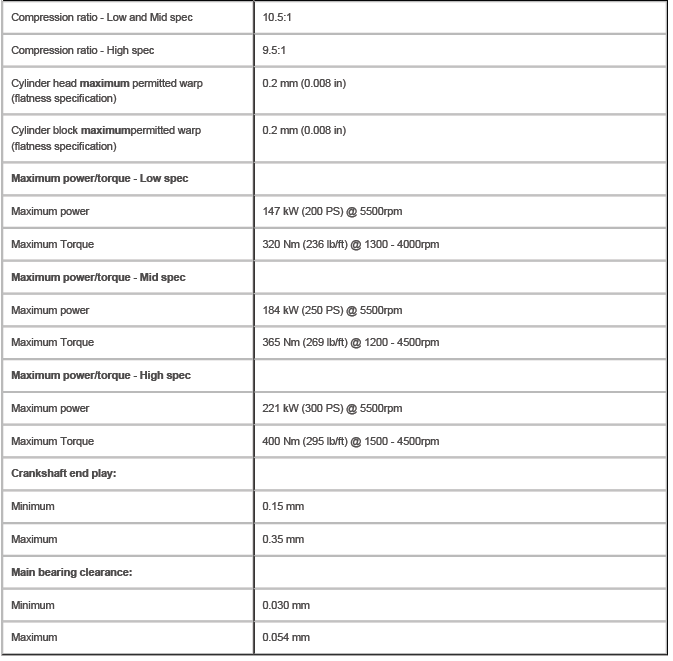
General Specification
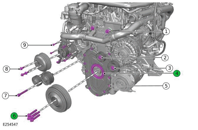
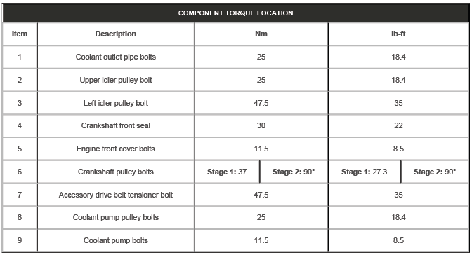
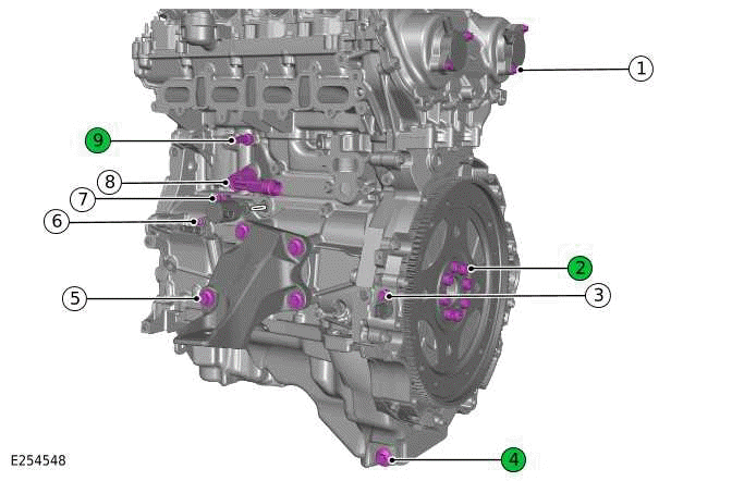
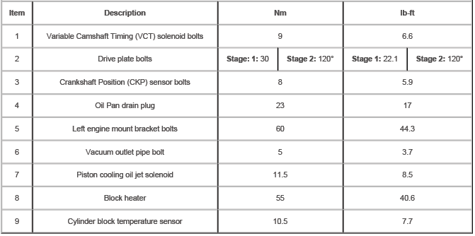
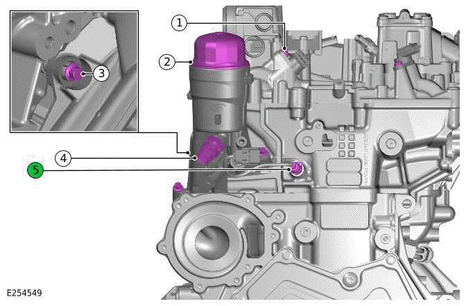
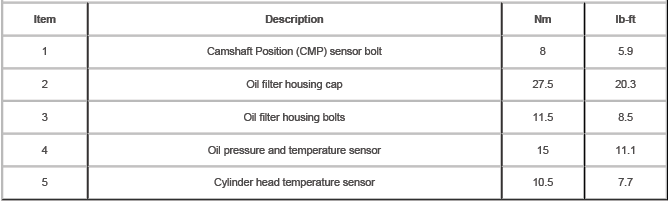
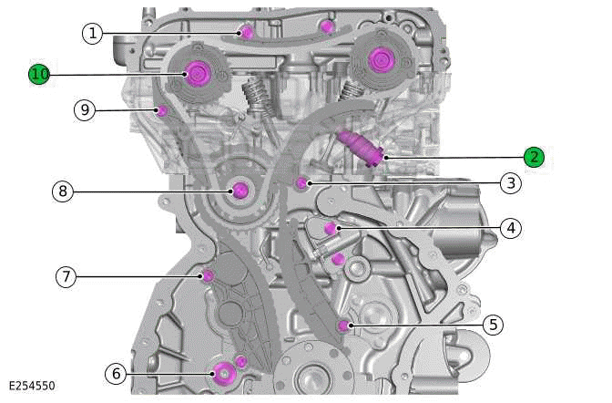
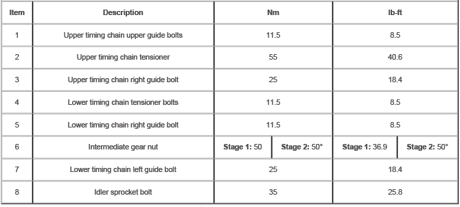
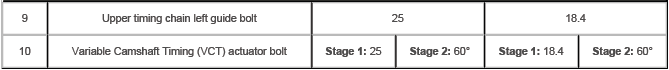
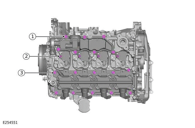
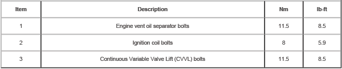
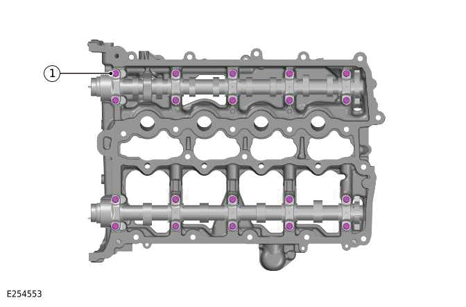
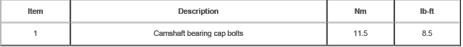
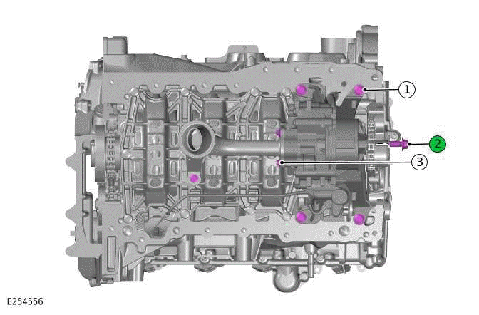
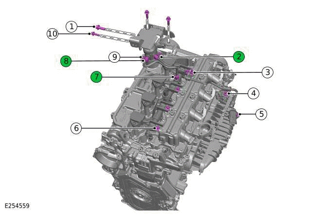
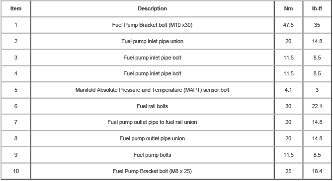
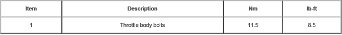
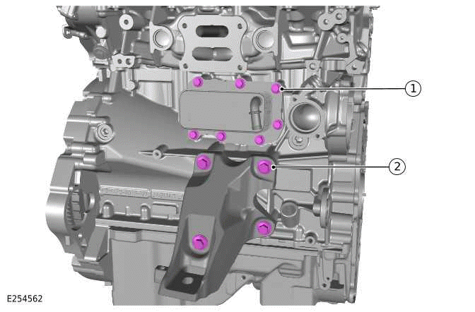
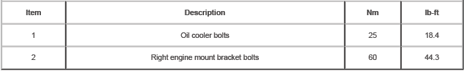
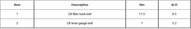
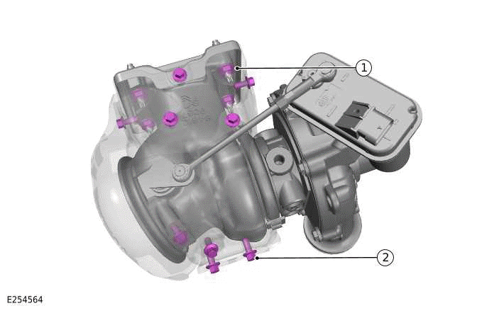
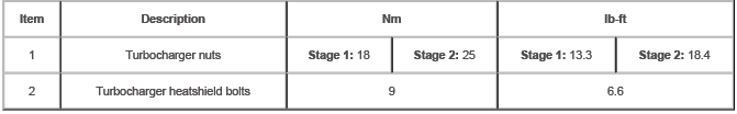
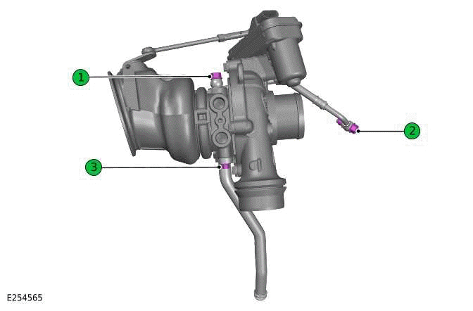
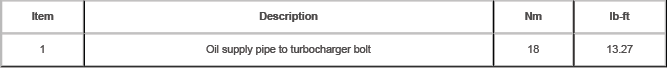
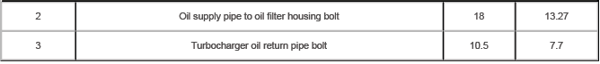
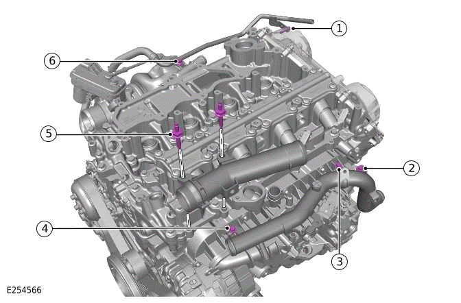
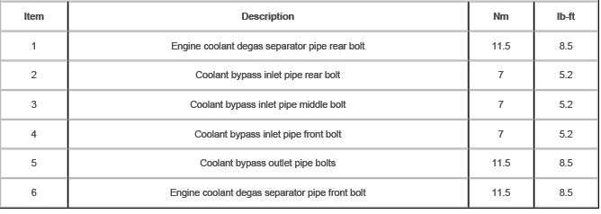
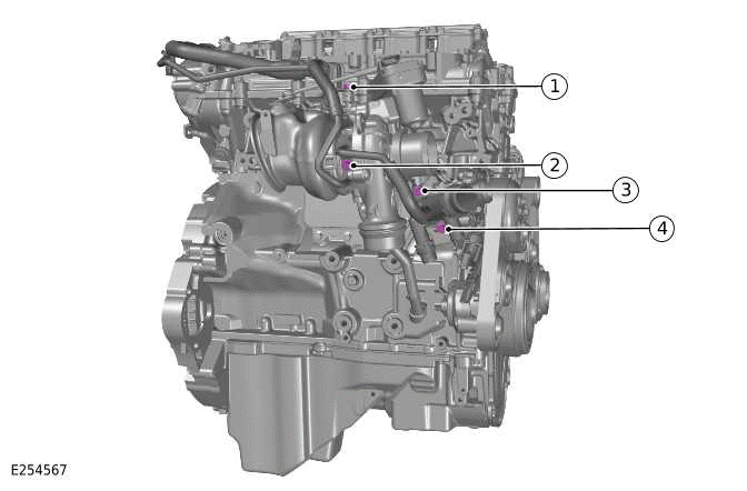
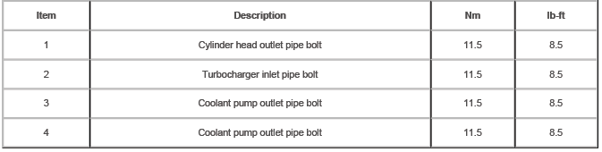
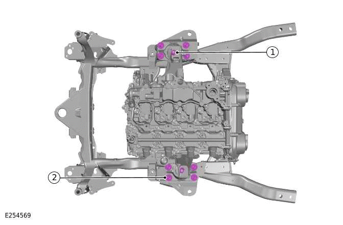
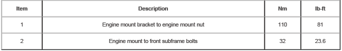
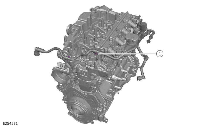
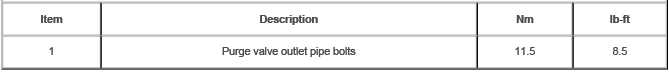
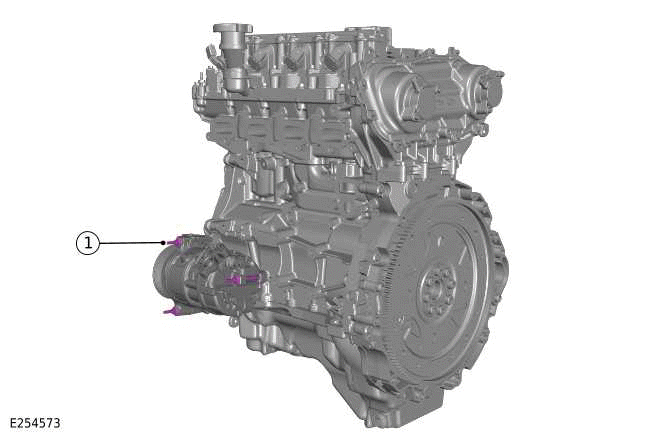
NOTE: Numbers with a green background are a single use component.
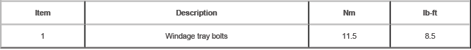
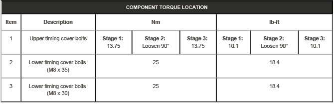
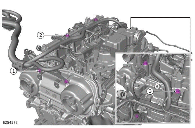
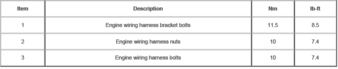
COMPONENT TORQUE LOCATION
COMPONENT TORQUE LOCATION
COMPONENT TORQUE LOCATION
COMPONENT TORQUE LOCATION
COMPONENT TORQUE LOCATION
COMPONENT TORQUE LOCATION
COMPONENT TORQUE LOCATION
COMPONENT TORQUE LOCATION
COMPONENT TORQUE LOCATION


COMPONENT TORQUE LOCATION
COMPONENT TORQUE LOCATION
COMPONENT TORQUE LOCATION
COMPONENT TORQUE LOCATION
COMPONENT TORQUE LOCATION
COMPONENT TORQUE LOCATION
COMPONENT TORQUE LOCATION
COMPONENT TORQUE LOCATION
COMPONENT TORQUE LOCATION
COMPONENT TORQUE LOCATION
COMPONENT TORQUE LOCATION
COMPONENT TORQUE LOCATION
COMPONENT TORQUE LOCATION
COMPONENT TORQUE LOCATION
COMPONENT TORQUE LOCATION
COMPONENT TORQUE LOCATION
COMPONENT TORQUE LOCATION
COMPONENT TORQUE LOCATION


- Engine - Description and Operation
- Engine - Diagnosis and Testing
- Engine Oil Vacuum Draining and Filling
- Crankshaft Pulley - Ingenium I4 2.0l Petrol
- Crankshaft Rear Seal - Ingenium I4 2.0l Petrol
- Camshafts - Engine Set
- Oil Cooler - Ingenium I4 2.0l Petrol
- Oil Filter Element
- Oil Pan - Ingenium I4 2.0l Petrol
- Oil Pump - Ingenium I4 2.0l Petrol
- Left Engine Mount - Ingenium I4 2.0l Petrol
- Right Engine Mount - Ingenium I4 2.0l Petrol
- Lower Timing Cover - Ingenium I4 2.0l Petrol
- Valves
- Camshaft Carrier
- Cylinder Head
- Upper Timing Chain
- Engine Front Cover - Ingenium I4 2.0l Petrol
- Intake Manifold - Ingenium I4 2.0l Petrol
- Upper Timing Cover
- Lower Timing Chain - Ingenium I4 2.0l Petrol
- Oil Filter Housing
- Oil Pump Drive Chain - Ingenium I4 2.0l Petrol
- Continuous Variable Valve Lift
- Continuous Variable Valve Lift Oil Temperature Sensor
- Variable Camshaft Timing Actuator
- Drive Plate - Ingenium I4 2.0l Petrol
- Engine - Removal
- Engine and Ancillaries - Removal
- Engine - Installation
- Engine and Ancillaries - Installation
READ NEXT:
 Component Location, Overview
COMPONENT LOCATION
COMPONENT LOCATION - EXTERNAL VIEW
OVERVIEW
The Ingenium I4 2.0L petrol engine is an inline 4 cylinder, turbocharged
engine that employs advanced modular
design principles.
The e
Description
CYLINDER BLOCK COMPONENTS
Bolt - Cylinder block front cover (quantity 14)
Cylinder block front cover
Cylinder block
Cylinder block rear cover and oil seal
Bolt - Cylinder block rear cover and o
SEE MORE:
Windshield Wiper Pivot Arm
REMOVAL AND INSTALLATION
REMOVAL
NOTES:
This procedure contains some variation in the illustrations depending
on the vehicle specification, but the
essential information is always correct.
This procedure contains illustrations showing certain components
removed to provide extra clarity.
1.
Map auto zoom
Make sure the relevant safety warnings
have been read and understood before
operating the navigation system.
When auto-zoom is enabled, the map
automatically zooms in when the vehicle
is traveling at slow speeds and zooms out
when traveling at higher speeds.
Auto-zoom can be enabled and disabled
v
