
Land Rover Defender: Upper Timing Cover
REMOVAL AND INSTALLATION
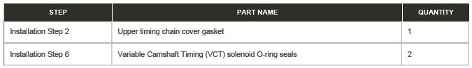
PART(S)
REMOVAL
WARNING: Be prepared to collect escaping coolant.
CAUTION: Before disconnecting any components, make sure the area is clean and free from foreign material. When disconnected all openings must be sealed.
NOTES:
- This procedure contains some variation in the illustrations depending on the vehicle specification, but the essential information is always correct.
- This procedure contains illustrations showing certain components removed to provide extra clarity.
1. Raise and support the vehicle on a suitable 2 post lift.
2. Disconnect the startup battery ground cable.
3. Partially drain the cooling system.
4. Remove the engine cover.
5. Remove the secondary bulkhead center panel.
6.
- Release the breather pipe from the clip.
- Reposition the breather pipe away from the bracket.
- Remove the bolt.
- Remove the bracket.
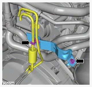
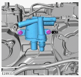
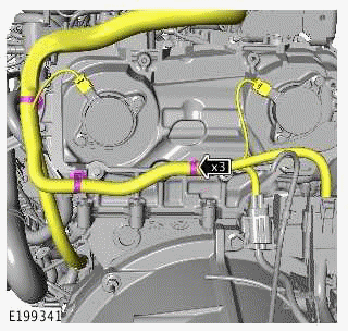
7.
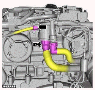
Disconnect the 3 coolant hoses.
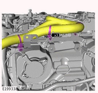
8.
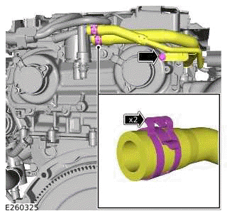
- Remove the bolt.
- Release the 2 hose clamps.
- Disconnect the 2 coolant hoses.
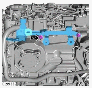
9.
- Remove the 2 bolts.
- Remove the engine coolant degas separator.
10.
- Release the 3 wiring harness clips.
- Reposition the engine wiring harness away from the bracket.
11.
- Remove the 2 bolts.
- Remove the wiring harness bracket.
12.
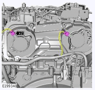
Disconnect the 2 electrical connectors from the Variable Camshaft Timing (VCT) solenoids.
13.
- Release the 3 wiring harness clips.
- Reposition the engine wiring harness away from the upper timing cover.
14.
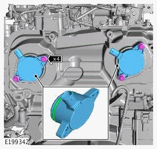
- Remove the 4 bolts.
- Remove the 2 VCT solenoids.
- Remove and discard the 2 O-ring seals.
15.
NOTE: If equipped.
Remove the Noise, Vibration and Harshness (NVH) material.
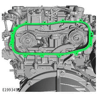
16.
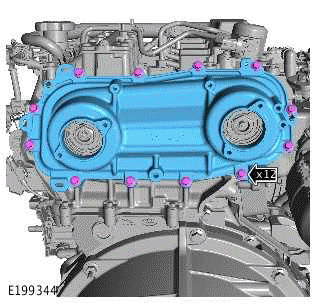
- Remove the 12 bolts.
- Remove the upper timing cover.
17.
Remove and discard the gasket.
INSTALLATION
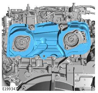
1.
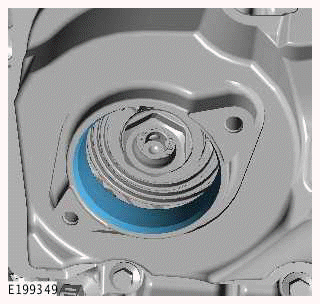
CAUTION: Make sure that all traces of the old sealant are removed from the mating surfaces.
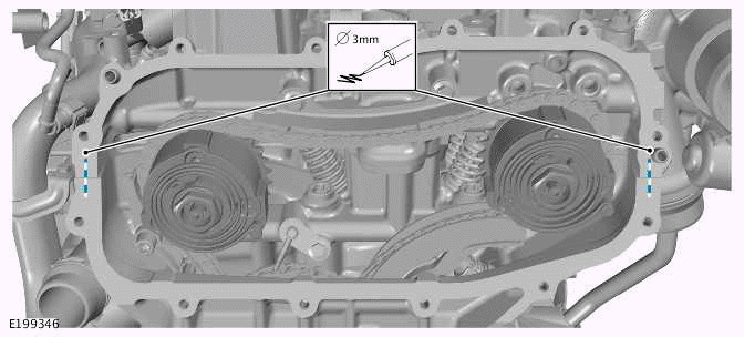
- Apply a 3 mm diameter bead of sealant to the area illustrated.
2.
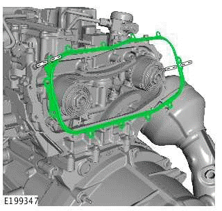
Install the new gasket.
3.
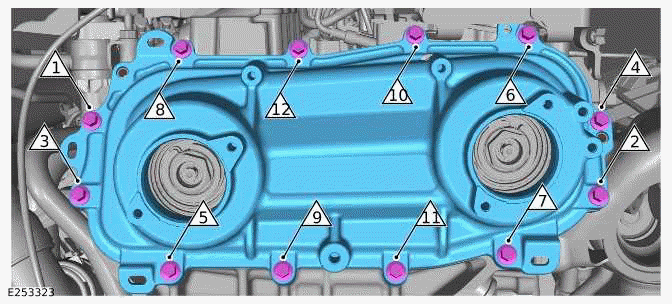
- Install the upper timing cover.
Torque
- Stage1: 13.5Nm
- Stage2: Loosen: 180º
- Stage3: 13.5Nm
4.
NOTE: If equipped.
Install the NVH material.
5.
Lubricate the VCT solenoid bores with clean oil.
6.
CAUTION: Make sure that the area around the component is clean and free of foreign material.
- Install the 2 new O-ring seals.
Renew Part: Variable Camshaft Timing (VCT) solenoid O-ring seals Quantity: 2.
- Install the 2 VCT solenoids.
- Install and tighten the 4 bolts.
Torque: 9Nm
7.
- Reposition the engine wiring harness in the correct location.
- Install the 3 wiring harness clips.
- Connect the 2 electrical connectors to the VCT solenoids.
8.
- Install the wiring harness bracket.
- Install and tighten the 2 bolts.
Torque: 10Nm
- Reposition the engine wiring harness in the correct location.
- Install the 3 wiring harness clips.
9.
- Install the engine coolant degas separator.
- Install and tighten the 2 bolts.
Torque: 10Nm
10.
- Connect the 5 coolant hoses to the degas separator.
- Install the 2 hose clamps.
- Install and tighten the bolt.
Torque: 10Nm
11.
- Install the bracket.
- Install and tighten the bolt.
Torque: 10Nm
- Install the breather pipe to the clip.
12. Install the secondary bulkhead center panel.
13. Install the engine cover.
14. Vacuum fill the cooling system.
15. Connect the startup battery ground cable.
READ NEXT:
 Lower Timing Chain - Ingenium I4 2.0l Petrol
REMOVAL AND INSTALLATION
SPECIAL TOOL(S)
JLR-303-1630
Locking Tool, Crankshaft Pulley
JLR-303-1635
Camshaft Setting Tool
JLR-303-1636
Locking Tool, Variable Camshaft Timing Actuator /
Unit
JLR-303
Oil Filter Housing
REMOVAL AND INSTALLATION
PART(S)
REMOVAL
WARNING:
The spilling of hot engine oil is unavoidable during this procedure, care must
be taken to prevent scalding.
NOTE:
This procedure contains some va
Oil Pump Drive Chain - Ingenium I4 2.0l Petrol
REMOVAL AND INSTALLATION
SPECIAL TOOL(S)
205-053
Retainer, Differential Pinion Flange
PART(S)
REMOVAL
NOTES:
This procedure contains some variation in the illustrations depending
on the vehicle
SEE MORE:
Child Seat - Group 1 I-size
CHILD SEAT - GROUP 1 I-SIZE - PART NUMBER:
VPLRS0578
REMOVAL AND INSTALLATION
WARNING:
Accessories which are not correctly installed can be dangerous. Read the
instructions carefully prior to
installation. Comply with instructions at all times. If in doubt, contact your
nearest approved retailer.
Front Infotainment Control Module
REMOVAL AND INSTALLATION
GENERAL EQUIPMENT
REMOVAL
NOTE:
This procedure contains some variation in the illustrations depending
on the vehicle specification, but the
essential information is always correct.
This procedure contains illustrations showing certain components
removed to provide e
