
Land Rover Defender: Description
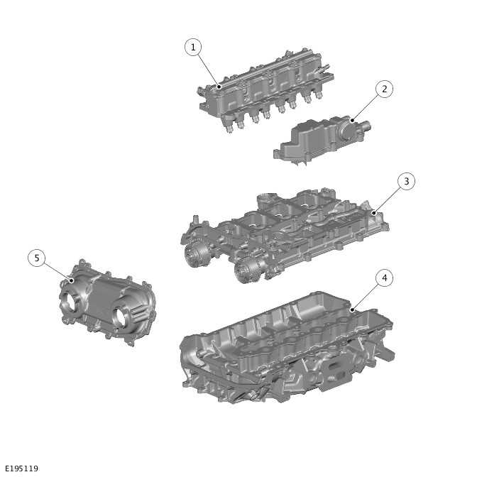
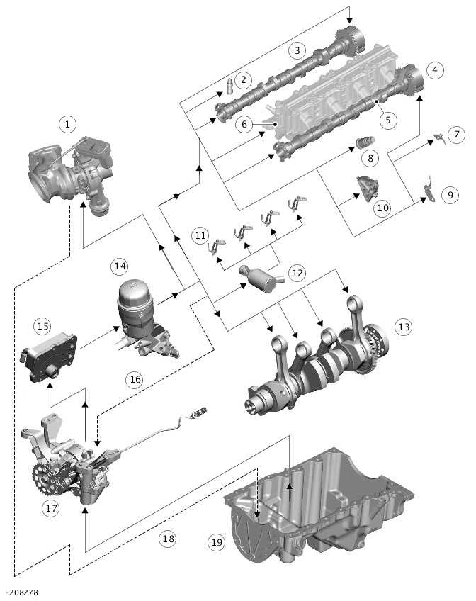
CYLINDER BLOCK COMPONENTS
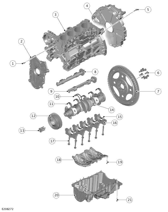
- Bolt - Cylinder block front cover (quantity 14)
- Cylinder block front cover
- Cylinder block
- Cylinder block rear cover and oil seal
- Bolt - Cylinder block rear cover and oil seal (quantity 16)
- Bolt - Drive plate (quantity 8)
- Drive plate
- Right dynamic balancer
- Left dynamic balancer
- Thrust washer (quantity 2)
- Upper main bearing (quantity 5)
- Crankshaft pulley/torsional vibration damper
- Bolt - Crankshaft pulley/torsional vibration damper (quantity 4)
- Crankshaft
- Lower main bearing (quantity 5)
- Main bearing cap (quantity 5)
- Bolts - Main bearing cap (quantity 10)
- Windage tray
- Bolt - Windage tray (quantity 12)
- Oil pan
- Bolt - Oil pan (quantity 16)
MAJOR STRUCTURAL COMPONENTS
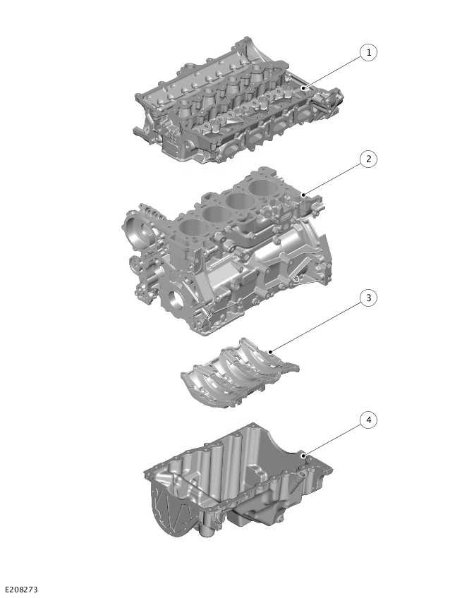
- Cylinder head
- Cylinder block
- Windage tray
- Oil pan
CYLINDER BLOCK
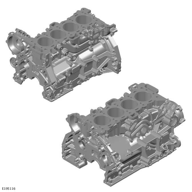
The deep skirt cast aluminum cylinder block is an inline configuration. Thin wall, interference fit cast iron liners provide optimum weight, cylinder bore roundness and robustness. The low volume engine coolant jacket gives good warm up times.
The cylinder block is a cross flow design with:
- The engine coolant inlet to the cylinder head on the exhaust side.
- And the engine coolant outlet from the cylinder head on the air inlet side.
Oil from the cylinder head drains back to the oil pan through open apertures. The first aperture located at the front of the cylinder block the second is at the rear of the cylinder block between the cylinder block and the rear cover.
A cast aluminum alloy, structural windage tray is bolted to the bottom of the cylinder block in purpose:
- To improve the cylinder block stiffness.
- To minimize Noise, Vibration and Harshness (NVH).
- To help reduce oil foaming.
Various machining ports in the cylinder block are sealed with cup plugs and threaded plugs. Removal of these is not necessary for service procedures.
There are a front cover and a rear cover on the engine. The front cover is secured to the cylinder block with bolts and sealed to the cylinder block with an injection molded gasket with RTV sealant at T joints. The rear cover is sealed with RTV sealant. Both cover contains a machined place for the oil seal. The front and rear covers have a removable element that allows the replacement of the oil seal without the removal of the cover.
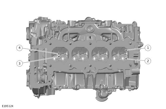
CYLINDER NUMBERING
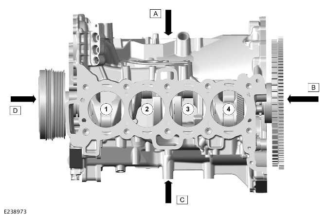
- Right of the engine
- Rear of the engine
- Left of the engine
- Front of the engine
- Number 1 cylinder
- Number 2 cylinder
- Number 3 cylinder
- Number 4 cylinder
The cylinders are numbered as shown, with cylinder 1 at the front of the engine
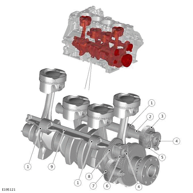
CRANKSHAFT
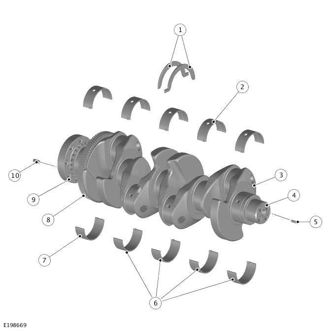
- Thrust washers (quantity 2)
- Upper main bearings (quantity 5)
- Crankshaft
- Crankshaft pulley/torsional vibration damper location
- Roll pin - Crankshaft pulley/torsional vibration damper
- Lower main bearing (quantity 4)
- Lower main bearing - Rear
- Dynamic balancer drive gear
- Timing chain drive sprocket
- Roll pin - Drive plate
The crankshaft is manufactured from forged carbon steel C38 MOD with induction hardened main and large end bearing journals. The fillets of the main and large end bearing journals are fillet rolled to improve the strength of the crankshaft.
The 5 counterweight design is used to reduce bearing loads as well as to give class leading vibration levels.
An oil groove in the upper half of each main bearing transfers pressurized engine oil into the crankshaft for lubrication of:
- The main bearings
- The connecting rod bearings.
There are 2 different lower main bearing designs. The first 4 lower main bearings do not have oil grooves. The fifth (rear) lower main bearing has partial grooves at each end.
The crankshaft assembly comprises the bare crankshaft and a dynamic balancer system drive gear. This gives direct drive at a ratio of 2:1 of the 2 counter rotating dynamic balancers.
The 2 individual thrust washers are located on either side of the central main bearing journal panel of the cylinder block to control crankshaft end float.
CRANKSHAFT INSTALLATION
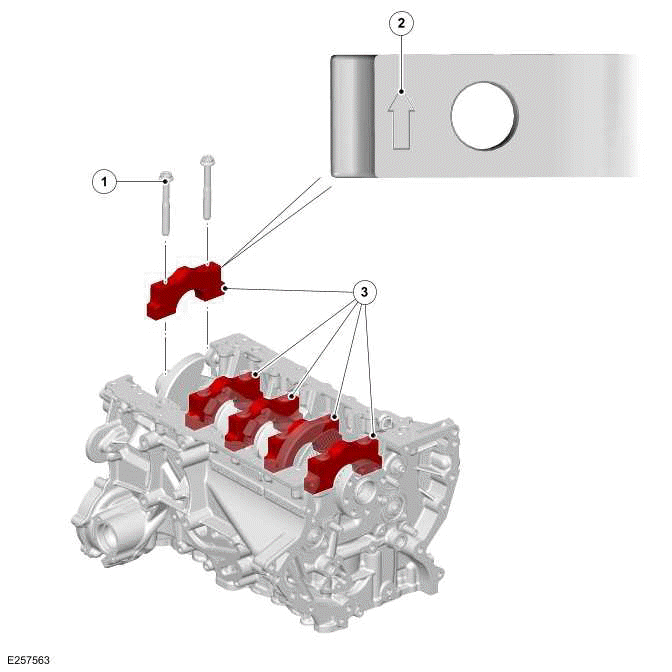
- Bolt - Main bearing cap (quantity 10)
- Orientation arrow
- Main bearing cap (quantity 5)
The crankshaft is retained in position by 5 main bearing caps that are manufactured from sintered steel. Each individual main bearing cap has a numbered identification (1-5) and an arrow to make sure that the location and orientation is correct. The arrow must face towards the front of the engine.
There are a number of grades of main bearing available. Each main bearing is color coded and inkjet marked with a number on the running face of the bearing. The crankshaft is laser etched with a string of 5 alpha characters in the order of the crankshaft main bearing journals 1-5. There is also a data matrix code containing the same data. make sure that the correct running clearance is obtained use the main bearing selection chart.
The main bearings in the cylinder block have a central hole and an internal groove to allow for main bearing journal lubrication. The main bearings in the main bearing caps are plain with no hole or internal groove.
CRANKSHAFT PULLEY/TORSIONAL VIBRATION DAMPER
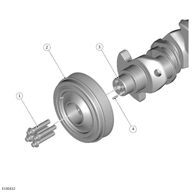
- Bolt - Crankshaft pulley/torsional vibration damper (quantity 4)
- Crankshaft pulley/torsional vibration damper
- Crankshaft
- Roll pin - Crankshaft pulley/torsional vibration damper
The crankshaft pulley/torsional vibration damper is located at the front of the crankshaft which drives the accessory drive belt for the ancillary components. A tuned torsional vibration damper is incorporated into the crankshaft pulley which dampens vibration in the crankshaft produced by the combustion process. Each time a cylinder fires, torque is applied to the crankshaft through the pistons and connecting rods. The crankshaft deflects in reaction to the torque that creates a vibration when the torque is dissipated. The torsional damper absorbs the vibration, reducing fatigue damage to the crankshaft.
The crankshaft pulley /torsional vibration damper is located on an alignment roll pin that is pressed into the front of the crankshaft. The 4 bolts are secure the crankshaft pulley/torsional vibration damper to the crankshaft. An O-ring seal provides a seal between crankshaft pulley/torsional vibration damper hub bore and the crankshaft nose outer diameter. This prevents oil leakage during engine operation. The crankshaft pulley /torsional vibration damper hub seals to the dynamic shaft oil seal of the front cover. If the crankshaft pulley /torsional vibration damper is removed the front oil seal must be replaced.
The crankshaft pulley /torsional vibration damper has a timing mark. When the timing mark aligns to the front cover assembly timing feature, the crankshaft is 50º After Top Dead Center (ATDC) for number 1 cylinder.
The crankshaft pulley /torsional vibration damper is not a serviceable component and must not be disassembled.
DRIVE PLATE
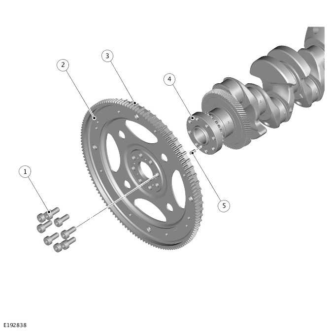
- Bolt - Drive plate (quantity 8)
- Drive plate
- Reluctor ring
- Crankshaft
- Dowel pin - Drive plate
The drive plate is located at the rear of the crankshaft. A dowel pin the crankshaft makes sure that the drive plate is indexed correctly.
The drive plate is a fabrication which comprises a formed steel starter ring gear which is attached to the drive plate and reluctor ring. The 2 components are held together as 1 assembly by a form of clinching known as Tog-L-Loc.
The drive plate is secured to the crankshaft by 8 sealant patched bolts. The bolts can only be used when and must be replaced if removed. Before replacement bolts are used, the holes must be dry and free from oil.
The drive plate has 3 functions:
- To transfer drive from the crankshaft to the transmission.
- To transfer drive from the starter motor to the crankshaft.
- To provide the PCM with crankshaft speed and position through a reluctor ring and a Crankshaft Position Sensor (CKP).
The reluctor ring has 58 teeth with 2 teeth missing to provide a gap. The CKP is located in the lower timing chain cover and measures rotational speed and position as the reluctor ring rotates.
The reluctor ring has a service tool slot used during engine service procedures. The drive plate incorporates a steel starter ring gear which enables the starter motor to start the engine.
The 4 holes in the drive plate provide for the attachment of the automatic transmission torque converter to transfer drive from the crankshaft to the automatic transmission.
PISTONS AND CONNECTING RODS
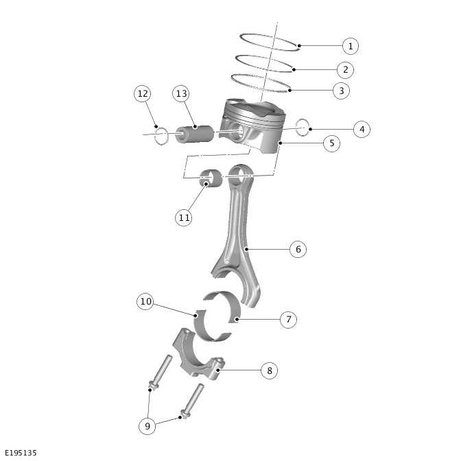
- Upper compression ring
- Lower compression ring
- Oil control ring
- Circlip
- Piston
- Connecting rod
- Large end bearing - Upper
- Connecting rod bearing cap
- Bolt - Connecting rod bearing cap (quantity 2)
- Large end bearing - Lower
- Small end bearing
- Circlip
- Gudgeon pin
The connecting rods are manufactured from forged steel and have fracture split connecting rod bearing caps to make sure precision reassembly for bearing alignment. The connecting rod bearing caps are not selectable. Adjustment for large end bearing journal size is made by selecting the correct large end bearings after measuring the crankshaft journals.
There are a number of grades of large end bearing available. Each size of the bearings is inkjet marked with a letter on the running face of the bearing. The crankshaft is laser etched with a string of 4 alpha characters in the order of crankshaft journals 1-4. A data matrix code contains the reference data for each large end bearing, installed to the engine. The correct large end bearings are sized with reference to a selection chart in order to achieve optimum running clearances.
There is only 1 grade of piston diameter. The top face of the pistons are marked with an arrow that must point towards the front of the engine to assure correct assembly. The piston crown has a recess for optimization of the fuel/air mixture and combustion.
The pistons use a 3 ring piston sealing system. An oil control ring is located in the lower groove. The 2 compression piston rings are located above the oil control ring. The piston ring gaps must be positioned at 120º to each other. The pistons are cooled with engine oil from 4 piston cooling oil jets installed in the cylinder block.
The pistons are attached to the connecting rods with a gudgeon pin, which is secured with 2 circlips. The gudgeon pin is located through the small end bearing in the connecting rod which allows the piston to articulate with the linear movement of the connecting rod. The 2 circlips locate in grooves in the piston.
DYNAMIC BALANCERS
- Bearing outer race (quantity 4)
- Dynamic balancer - Left
- Gear - Left dynamic balancer
- Bolt (quantity 2)
- Bearing
- Bearing
- Idler gear
- Gear - Right dynamic balancer
- Dynamic balancer - Right
The engine balance system consists of 2 eccentric weighted dynamic balancer shafts which oppose vibrations created by the reciprocating components of the engine. The dynamic balancers are mounted on outer races, pressed into machined bores inside the cylinder block. The 2 dynamic balancers rotate in opposite directions, driven at twice the speed of the crankshaft by a dynamic balancer gear, pressed onto the crankshaft. The equally sized eccentric weights are phased so that the inertia reaction to their counter rotation cancels out vibration, caused by the engine.
The left dynamic balancer has a 43 teeth drive gear that is driven by the 86 teeth ring gear on the crankshaft. The right dynamic balancer is also driven by the 86 teeth ring gear by a 45 teeth idler gear. The idler gear makes sure that the 2 dynamic balancers rotate in opposite directions.
The idler gear is mounted on to the cylinder block using a steel idler bush which is pressed into the cylinder block.
Driven gears on 1 of the dynamic balancers and the idler gear are anti backlash "scissor" gears in order to minimize noise. All the gears are helical to make sure that they operate smoothly. The dynamic balancers are located on needle roller bearings that run on outer races installed in the cylinder block machined bores. The bearings are lubricated by oil mist during engine operation.
It is important to make sure that each dynamic balancer is timed correctly in respect to the crankshaft using specialized alignment tool(s).
OIL PAN
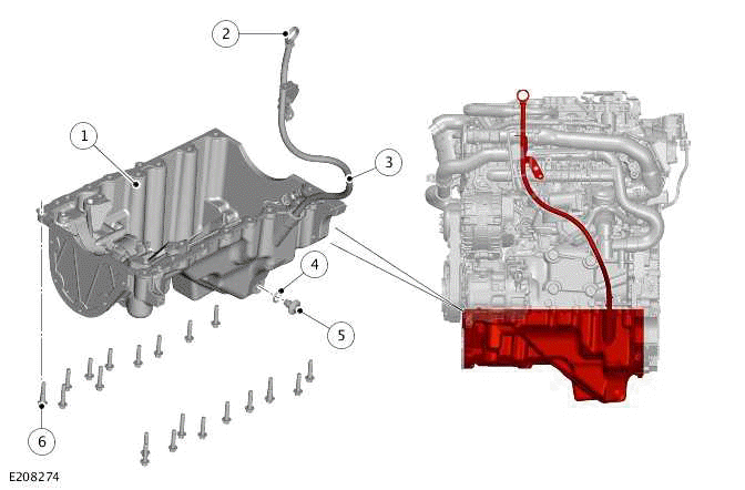
- Oil pan
- Oil level gauge
- Oil level gauge tube
- Sealing washer
- Oil pan drain plug
- Bolt - Oil pan (quantity 20)
The oil pan is cast from aluminum alloy using a HP die cast process and is located on the underside of the cylinder block. The oil pan is sealed to the cylinder block with RTV sealant. The oil pan is secured with 14 bolts and 2 shoulder bolts that locate the oil pan to the cylinder block. The oil pan contains the windage tray and the oil level gauge tube.
The oil is drained by removal of the oil pan drain plug and washer, located on the side of the oil pan. Use new oil pan drain plug and washer after they are removed.
CYLINDER HEAD
Cylinder Head Structural Components
- Continuously Variable Valve Lift (CVVL) assembly
- Engine vent oil separator
- Camshaft carrier
- Cylinder head
- Timing chain cover
Cylinder Head Components
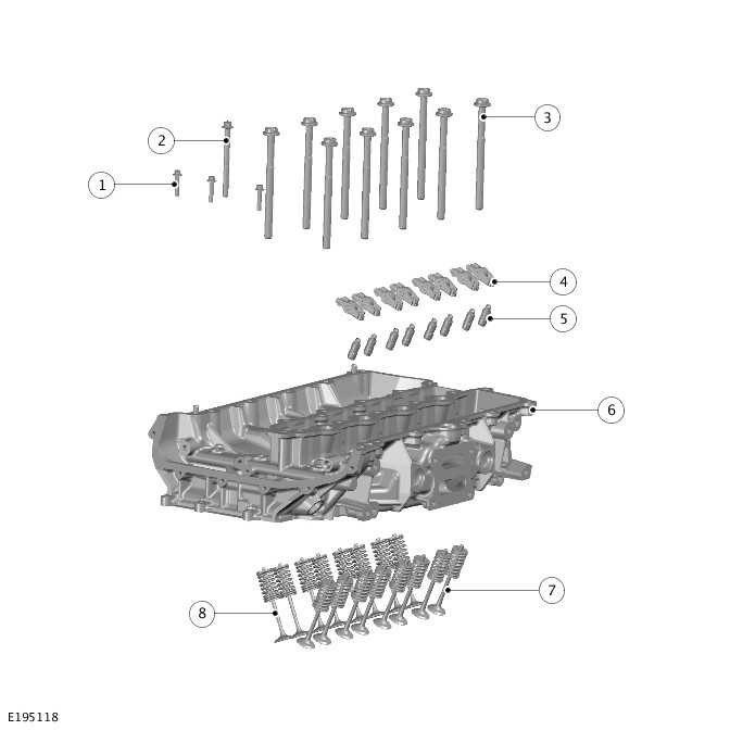
- Bolt (quantity 3)
- Bolt
- Bolt - Cylinder head (quantity 10)
- Roller finger cam follower - Exhaust (quantity 8)
- Hydraulic valve tappet - Exhaust (quantity 8)
- Cylinder head
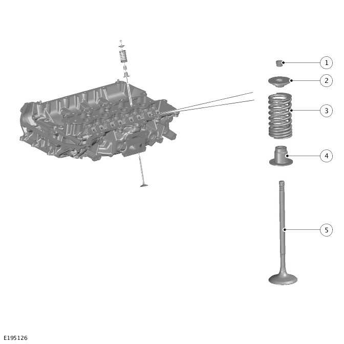
- Exhaust valve assembly (quantity 8)
- Intake valve assembly (quantity 8)
The cylinder head is cast from aluminum alloy and heat treated. The cylinder head provides location for 16 valves, 4 injectors, 4 spark plugs and 1 cylinder head temperature sensor. The cylinder head is cooled by a double layer water jacket.
There are 14 bolts to secure the cylinder head to the cylinder block. The cylinder head bolts can only be used when and must be replaced if they are removed. Before replacement bolts are used, make sure that the bolt holes and threads in the cylinder block are dry and free from oil.
The cylinder head assembly contains the following parts:
- A cylinder head
- A camshaft carrier
- A Continuously Variable Valve Lift (CVVL) assembly
- An engine vent oil separator
- A timing chain cover.
Each cylinder has 4 valves, 2 intake and 2 exhaust valves. To help achieve the required gas flow characteristics, these are arranged asymmetrically around the cylinder bore. Each cylinder has a fuel injector and a spark plug.
The valves are a conventional arrangement, with a valve and spring assembly retained by a valve collet. The exhaust hydraulic valve tappet makes sure, that no lash between the camshaft lobe and the roller finger cam follower.
The cylinder head gasket is of a multi layer steel construction.
- Exhaust valve (quantity 8)
- Intake valve (quantity 8)
- Fuel injector (quantity 4)
- Spark plug (quantity 4)
CAMSHAFT CARRIER
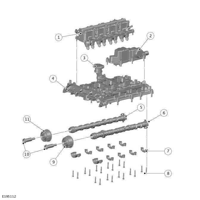
- Continuously Variable Valve Lift (CVVL) assembly
- Engine vent oil separator
- Oil filler cap
- Camshaft carrier
- Intake camshaft
- Exhaust camshaft
- Camshaft cap (quantity 10)
- Bolt - Camshaft cap (quantity 10)
- VCT actuator - Exhaust
- Bolt - VCT actuator (quantity 2)
- VCT actuator - Intake
The structural camshaft carrier is cast from aluminum alloy using a high pressure die cast process. The camshaft carrier is located on 2 dowel pins in the cylinder head and secured with bolts. A gasket seals the camshaft carrier to the cylinder head.
The primary function of the camshaft carrier is to house and secure the intake and exhaust camshafts. The camshaft carrier bore geometry is bored in a single machining operation to make sure optimum friction reduction. Each camshaft cap is uniquely identified and must be matched to its related bore.
The camshaft carrier also provides locations for the CMP, the oil filler pipe and the engine vent oil separator. The camshaft carrier has high pressure oil bores feeding the hydraulic VCT actuators and provides thrust face lubrication.
A low pressure oil gallery returns oil from the engine vent oil separator, back to the cylinder block and the oil pan.
VALVES AND ROLLER FINGER CAM FOLLOWERS
Exhaust Valves And Roller Finger Cam Followers
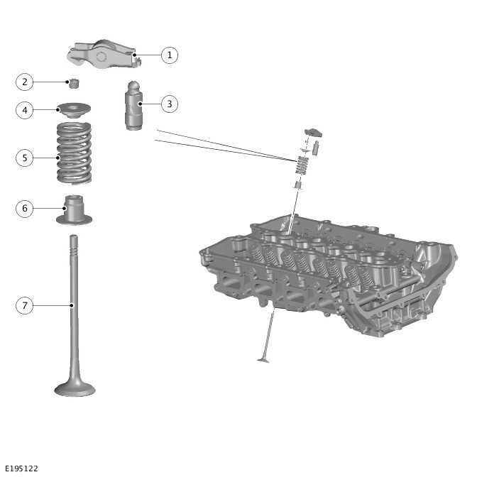
- Roller finger cam follower (quantity 8)
- Valve spring collets (quantity 16)
- Hydraulic valve tappet (quantity 8)
- Valve spring retainer (quantity 8)
- Valve spring (quantity 8)
- Valve spring seat and valve stem seal (quantity 8)
- Exhaust valve (quantity 8)
Intake Valves
- Valve spring collets (quantity 16)
- Valve spring retainer (quantity 8)
- Valve spring (quantity 8)
- Valve spring seat and valve stem seal (quantity 8)
- Intake valve (quantity 8)
The engine uses 16 chrome plated steel valves, 8 intake and 8 exhaust valves.
The larger intake valve size provides better intake air flow into the combustion chamber, which enhance more engine power output at higher RPM. The intake and exhaust valve stems are allow reduced flow interruption through the intake and exhaust ports, improving performance and emissions.
The valves are located in conventional, non serviceable valve guides in the cylinder head. A valve stem seal with integral spring seat is located in the cylinder head. The valve spring is retained in a compressed state on the valve stem by a valve spring retainer and a pair of valve spring collets.
The exhaust valves are opened mechanically by the roller finger cam followers which operate directly with roller to camshaft lobe rolling contact. The clearance between the roller and camshaft lobe is compensated with the use of the hydraulic valve tappet. This makes sure that all roller finger cam followers are in contact with the camshaft lobes throughout engine operation.
The intake valves are opened by the Continuously Variable Valve Lift (CVVL) assembly that is controlled by the PCM.
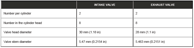
CAMSHAFTS
- Intake camshaft
- Needle roller bearing (quantity 10)
- Intake camshaft lobe (quantity 4)
- Reluctor ring - CMP
- Exhaust camshaft lobe (quantity 8)
- Lobe - HP fuel pump
- Exhaust camshaft
The engine is equipped with a Double Overhead Camshaft (DOHC) configuration which uses 2 camshafts:
- The intake camshaft
- The exhaust camshaft.
The lobes on the exhaust camshaft control the opening and closing of the exhaust valves through the roller finger cam followers. There is 1 lobe that drives the HP fuel pump. The lobes on the intake camshaft control the opening and closing of the intake valves through the Continuously Variable Valve Lift (CVVL) assembly.
The camshafts run on needle roller bearings to reduce friction and minimize the breakaway torque on engine startup.
The needle roller bearings are housed in the camshaft carrier and the camshaft caps are marked with 'I' and 'E' to denote inlet and exhaust. The camshaft caps are also numbered to make sure assembly in the correct position in the camshaft carrier. For example 'I4' or 'E1'.
The camshafts are of a hollow steel tube construction, with pressed on forged lobes and needle roller bearings. The hollow tube design provides reduced weight for increased engine performance. Each camshaft has a pressed on drive adapter which locates a drive sprocket and the VCT actuator. Each drive adapter is equipped with a timing pin. The timing pin helps to locate and time the rotor of the VCT actuator relative to the camshaft during assembly. Each camshaft has a pressed on reluctor ring for use with the CMP.
The VCT sprocket is driven by the crankshaft through the timing chain. The torque is transmitted from the VCT sprocket to the camshaft by hydraulic means. The VCT actuator adjusts the timing of both camshafts, increasing engine efficiency and performance as required. The reluctor wheels are pressed on to the opposite end of the exhaust camshafts which are monitored by the CMP. The CMP signal is used by the PCM and enables the PCM to determine the position of the camshafts. The camshafts can then be phased by the VCT actuators.
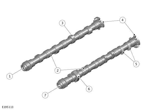
TIMING CHAIN
- Intake camshaft
- VCT actuator - Intake
- Secondary timing chain
- Secondary timing chain guide
- VCT actuator - Exhaust
- Exhaust camshaft
- Secondary timing chain tensioner guide
- Secondary timing chain tensioner
- Primary timing chain tensioner
- Primary timing chain tensioner guide
- Crankshaft
- Primary timing chain guide
- Primary timing chain
- Idler sprocket
- Secondary timing chain guide
There are 2 bushed timing chains are used to drive the camshafts through an intermediate idler sprocket. The primary camshaft chain is driven by a sprocket on the crankshaft which in turn drives the intermediate idler sprocket. The secondary camshaft chain is driven by the intermediate idler sprocket and then passed over the sprockets on the intake and exhaust camshafts. The camshaft sprockets are integrated with the VCT actuator assemblies.
The primary timing chain has a fixed timing chain guide which is secured to the cylinder block. A chain tensioner is secured to the primary timing chain tensioner guide. The timing chain tensioner guide can rotate around a pivot bolt.
The primary timing chain has a mechanical tensioner, operated by spring tension to apply a controlled tension to the timing chain. The primary timing chain tensioner receives pressurized engine oil from the variable flow oil pump with integral vacuum pump.
The secondary timing chain has 2 fixed timing chain guides which are secured to the cylinder head and the camshaft carrier. The secondary timing chain has a hydraulic secondary chain tensioner which receives pressurized engine oil from the variable flow oil pump with integral vacuum pump.
The tensioners maintain the timing chains at the correct tension and allow for and dampens backlash in the chain tension due to engine deceleration. The timing chains and tensioners are maintenance free components.
A procedure and special tools are required to make sure that the correct crankshaft to camshaft timing is achieved.
Both the primary and secondary timing chains have gold colored links which are aligned with timing marks on the sprockets.
VARIABLE CAMSHAFT TIMING
- VCT solenoid - Intake
- VCT actuator - Intake
- Secondary timing chain
- VCT actuator - Exhaust
- VCT solenoid - Exhaust
The PCM controls the system using information from the CMP and the CKP.
The timing of the intake and exhaust camshafts can be adjusted independently by an oil pressure controlled torsional assist VCT system. The VCT solenoid that is controlled electrically determines the position of the VCT actuator which has a direct interface with the camshafts.
Each VCT actuator is located on the camshaft at the front of the engine and is secured with a center bolt. Each center bolt contains an oil control valve.
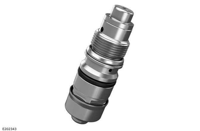
Variable Camshaft Timing Actuator
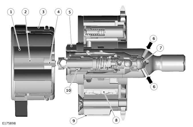
- Solenoid coil
- Solenoid core
- VCT solenoid assembly
- Solenoid pintle pin
- Center bolt
- Pressurized engine oil supply
- Filter
- Rotor
- VCT actuator housing
- Spool valve
The VCT actuators are operated by the VCT solenoids that are controlled by the PCM. The PCM can operate the VCT solenoids to move the pintle pin to a predetermined position to control the flow of pressurized engine oil into the VCT actuators.
When advance or retard of the camshaft timing is required:
- The VCT solenoid operates,
- Extending the pintle pin,
- And moving the spool valve to direct pressurized engine oil into one side or the other of the central rotor chambers in the VCT actuator.
The solenoid pintle moves towards the spool valve located in the center bolt and makes contact.
Further movement of the solenoid pintle pin will push the spool valve into a known (controlled) position and oil will pass through channels within the center bolt into the VCT actuator chambers. The pressurized engine oil rotates the internal rotor in the VCT actuator which is secured to the camshafts. This in turn changes the engine timing.
The available camshaft adjustment is the following:
- Total 70º crankshaft angle towards advance in the intake camshaft.
- Total 50º crankshaft angle towards retard in the exhaust camshaft.
Each camshaft VCT actuator has 3 hydraulic chambers. Residual camshaft torque is used to make sure the VCT actuator is returned to the 'base' position as quickly as possible. The pressurized engine oil is supplied from the variable flow oil pump and must be mapped to deliver a controlled oil pressure to the VCT actuator.
CONTINUOUSLY VARIABLE VALVE LIFT ASSEMBLY
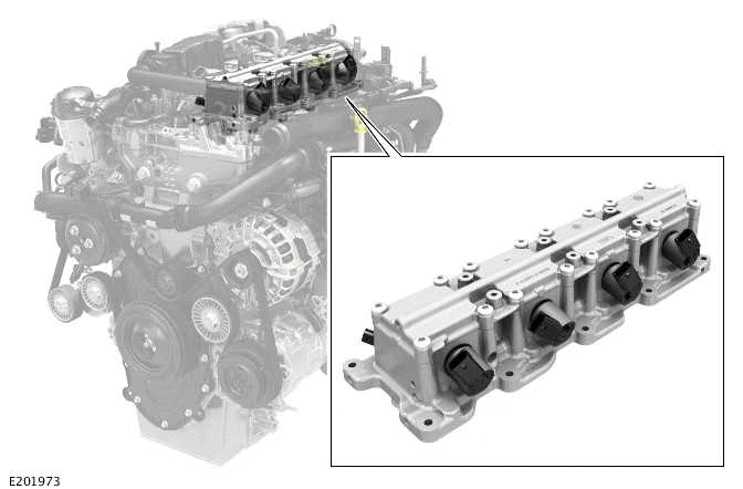
The Continuously Variable Valve Lift (CVVL) assembly is a non-serviceable assembly for control of the intake valve lift. The CVVL assembly temperature sensor can be removed from the CVVL assembly if required. The CVVL assembly is fixed to the top of the camshaft carrier by 10 bolts.
There is no mechanical connection between the intake valves and the camshaft. Instead of direct operation, the intake camshaft operates 4 small oil pumps which charge 4 hydraulic accumulators.
- Intermediate pressure chamber
- Solenoid valve
- Pressure accumulator
- Cam follower
- Camshaft
- Intake valve
- Brake unit
- Continuously Variable Valve Lift (CVVL) oil temperature sensor
- High pressure chamber
- Pump unit
As the camshaft rotates, the cam lobe lift translates to pump piston movement and creates the hydraulic pressure achieved within the unit. The high pressure chamber is the hydraulic connection between the pump, brake unit and solenoid valve where pressures can be reached up to 150 bar (2,175 psi).
When the solenoid valve is closed the oil operates as a 'hydraulic pushrod' through the brake unit opening the intake valve. When the solenoid valve is opened, some of the oil pressure is relieved from the high pressure chamber back in to the intermediate pressure chamber. This is effectively 'shortening' the length of the 'hydraulic pushrod' and the amount of valve lift.
When the solenoid valve is opened, the pressure accumulator feeds the relieved oil back to the high pressure chamber. The relieved oil makes sure that the chamber has a constant de-aerated oil supply. The brake unit, as well as acting as a hydraulic valve lash adjustment, also regulates the valve closing speed.
When the solenoid is opened for early intake valve closing, the valve spring causes the valve to enter a 'ballistic flight phase'. That is an 'uncontrolled' period of travel as the valve does not close by following the cam profile. To prevent excessive closure speeds that can cause damage to the valve, the brake unit acts as a hydraulic brake to provide a gentle, controlled seating of the valve.
The solenoid switching time is controlled by the PCM, based on calculated engine load, engine speed and oil temperature values from existing sensors. The CVVL oil temperature sensor is the only additional sensor for the system.
Schematic View - Continuously Variable Valve Lift Hydraulic Circuit
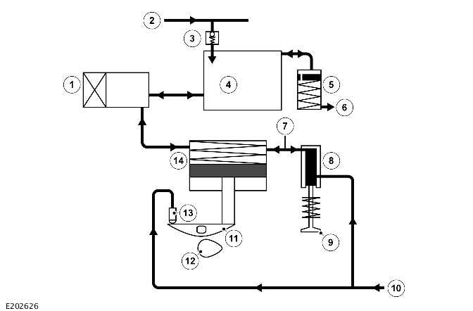
- Solenoid valve
- Engine oil supply
- Check valve
- Intermediate chamber
- Pressure accumulator
- Oil return
- Continuously Variable Valve Lift (CVVL) oil temperature sensor
- Brake unit
- Intake valve
- Engine oil supply
- Roller finger cam follower
- Camshaft
- Hydraulic tappet
- Pump unit
CAUTION: Use only engine oil that meets Jaguar Land Rover (JLR) specification. Using incorrect engine oil can cause the Continuously Variable Valve Lift (CVVL) system to malfunction.
The CVVL assembly ultimately allows the control of air in to the cylinder by delaying the valve opening, or by closing the valve early.
There are 4 CVVL operating modes:
- Full lift mode - The valves are fully opened and closed as during conventional control by the camshaft. This mode is used at high engine speeds to obtain maximum engine power.
- Late intake valve opening mode - The opening of the intake valves are delayed when starting the engine and during the engine idle. The valves open for a shorter period and at a lower lift providing precise control of the exact amount of air entering the cylinder. As a result, fuel economy is improved during idling periods. During a cold start, only a small amount of cold air enters the cylinder, meaning the engine starts more easily.
- Early intake valve closing mode - This mode is activated during low to medium engine speeds. The intake valves are closed hydraulically before the camshaft profile would normally allow. This mode reduces pumping losses, increases the engine output and prevents an undesirable backflow of the fuel mixture into the intake ports.
- Composite mode - This mode is activated at very low engine speeds and loads. Composite mode is a combination of the late intake valve opening and the early intake valve closing modes, and it provides a stable combustion.
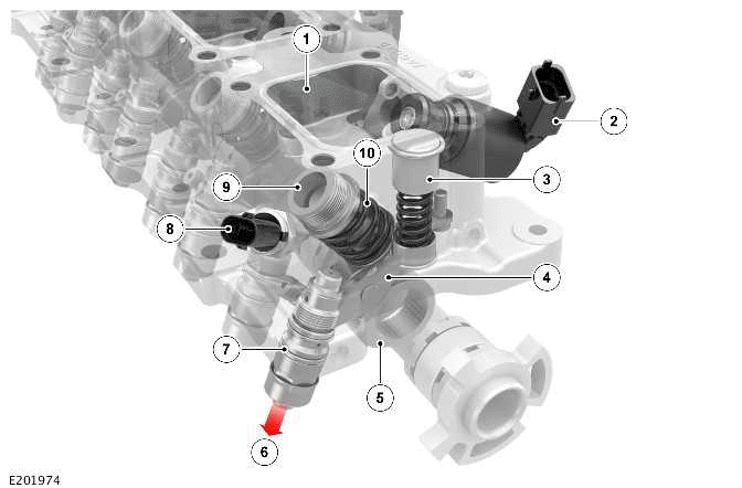
Continuously Variable Valve Lift Solenoid Valve
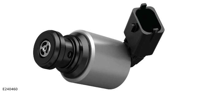
NOTE: The Continuously Variable Valve Lift (CVVL) solenoid valves cannot be replaced individually. In the event of a solenoid failure, the entire CVVL assembly must be replaced.
There are 4 solenoid valves used in the CVVL system, 1 per cylinder. Each CVVL solenoid valve is supplied with power supply and ground from the PCM. The PCM controls the solenoid position, using Pulse Width Modulated (PWM) signals.
To enable the rapid action of the solenoid valve, a special operating strategy was developed with the lowest possible current requirements. This resulted in a current profile consisting of several phases.
The solenoid normally has no power supply and is in the open position. At the first phase of activation the CVVL solenoid valve is supplied with a current, which pre-magnetise the solenoid but does not switch the valve.
In order to allow a rapid and precise energizing procedure, an increased current is applied at the exact time of switching. The current is determined by the PCM depending on sensor input for the current operating conditions.
After the CVVL solenoid valve is fully activated, the current is reduced to a holding current, which maintains the solenoid valve in the closed position. Depending on operating conditions, the PCM software controls the point in time at which the solenoid opens by completely switch off the holding current.
In the event of a CVVL solenoid failure, a total loss of valve lift occurs on the related cylinder and the engine enters a 'limp-home' mode, running on the 3 remaining cylinders. In this case, the driver can experience misfires and a reduction in engine performance.
Continuously Variable Valve Lift Brake Unit
The CVVL brake unit is a slave cylinder that converts the hydraulic pressure into the intake valve movement. The pump unit hydraulic pressure is converted through a hydraulic valve lash adjustment element in the CVVL brake unit.
The brake unit design not only gives a controlled closure of the valve but also enables a rapid opening speed. The rapid opening is because as the braking element of the unit is by-passed by the use of a check valve during the opening phase.
It is a critical part of the unit set up that the valve lash adjustment is reset. The valve lash adjustment must be completed when the unit is removed from the cylinder head.
Where it is necessary to remove and reinstall the CVVL assembly, the brake pistons must be reset. After the CVVL assembly installation the CVVL software calibration must be completed using the Jaguar Land Rover (JLR) approved diagnostic equipment.
Continuously Variable Valve Lift Oil Temperature Sensor
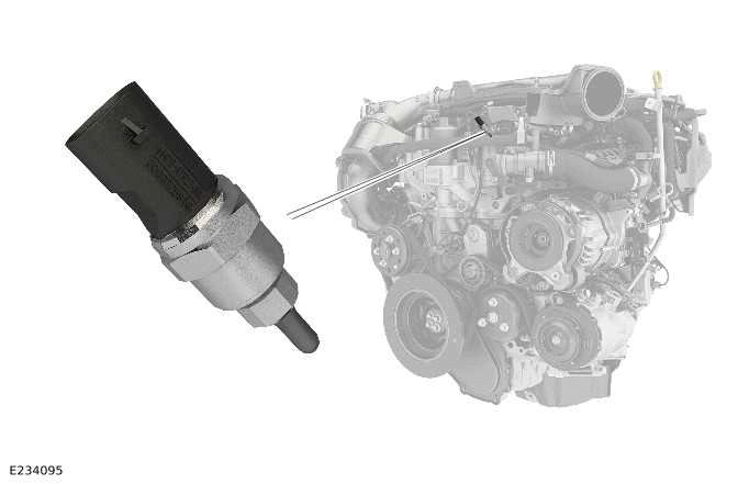
The CVVL oil temperature sensor is located at the front of the CVVL assembly. The sensor provides feedback to the PCM on the temperature of the high pressure oil in the CVVL assembly.
The PCM determines the oil viscosity and allows accurate solenoid switching time compensation across a wide engine temperature range -40ºC (-40ºF) to 150ºC (302ºF). The sensor has a 2 pin connector which provides a temperature signal input to the PCM and a ground connection. The sensor has a Negative Temperature Coefficient (NTC) element and is specifically calibrated for use at low temperatures.
When the CVVL oil temperature sensor fails, there is reduced accuracy in the control of the CVVL system. The reduced accuracy causes a slight reduction in performance and fuel economy.
ENGINE OIL LUBRICATION
Lubrication System Components
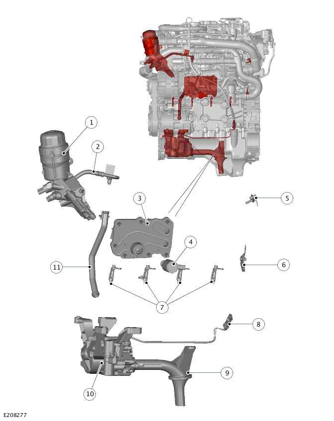
- Oil filter and housing
- Oil supply pipe - Turbocharger
- Engine oil cooler
- Piston cooling oil jets solenoid
- Secondary timing chain oil jet
- Primary timing chain oil jet
- Piston cooling oil jet (quantity 4)
- Variable flow oil pump solenoid electrical connector
- Variable flow oil pump inlet pipe
- Variable flow oil pump with integral vacuum pump
- Oil return pipe - Turbocharger
LUBRICATION SYSTEM FLOW DIAGRAM
- Turbocharger
- Hydraulic valve tappet - Exhaust valve (quantity 8)
- Exhaust camshaft
- VCT actuator (quantity 2)
- Intake camshaft
- Continuously Variable Valve Lift (CVVL) assembly
- Secondary timing chain oil jet
- Secondary timing chain tensioner
- Primary timing chain oil jet
- Primary timing chain tensioner
- Piston cooling oil jet (quantity 4)
- Piston cooling oil jet solenoid
- Crankshaft
- Oil filter and housing
- Engine oil cooler
- Engine oil pressure feedback to variable flow oil pump with integral vacuum pump
- Variable flow oil pump with integral vacuum pump
- Oil return pipe - Turbocharger
- Oil pan
The engine oil is drawn from the oil pan and pressurized by the variable flow oil pump with integral vacuum pump. The output from the variable flow oil pump with integral vacuum pump passes through oil drilling to be filtered through the oil filter. The output from the oil filter is distributed through oil drilling in the cylinder heads and the cylinder block.
The engine oil lubricates, cools and actuates various engine components. The engine oil lubricates all the moving parts in the engine by pressurized or splashed engine oil. The engine oil also while in contact with the engine components removes heat. In the oil cooler, the heat from the engine oil transferred to the engine coolant.
Pressurized engine oil is distributed from the variable flow oil pump with integral vacuum pump to the following:
- The oil cooler
- The oil filter
- The connecting rod large end bearing (quantity 4)
- The crankshaft main bearing (quantity 5)
- The intake camshaft
- The exhaust camshaft
- The VCT system
- The piston cooling oil jet (quantity 4) controlled by the piston cooling oil jet solenoid
- The primary timing chain tensioner
- The primary timing chain oil jet
- The secondary timing chain tensioner
- The secondary timing chain oil jet
- The turbocharger
- The hydraulic valve tappets
- The Continuously Variable Valve Lift (CVVL) assembly
- The timing chain tensioner
The oil returns to the oil pan under gravity. Large drain holes through the cylinder head and the cylinder block make sure that the engine oil returns rapidly to the oil pan. The engine oil is replenished through the oil filler cap on the camshaft cover. An oil drain plug is installed in the side of the oil pan.
VARIABLE FLOW OIL PUMP WITH INTEGRAL VACUUM PUMP
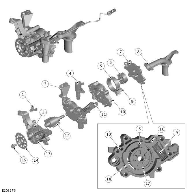
- Vacuum exhaust valve
- Engine oil outlet to cylinder block
- Center plate
- Oil pressure control solenoid
- Control ring
- Vanes and rotor assembly
- Oil pump cover
- Oil pump inlet pipe
- Control spring
- Oil pump housing
- Vacuum port connection to cylinder block
- Vacuum pump vanes
- Vacuum pump housing
- Oil pump drive sprocket
- Bolt
- Control ring oil pressure surface
- Oil pump rotor
- Oil pump vane (quantity 7)
The variable flow oil pump with integral vacuum pump is attached to the cylinder block with 4 bolts. The input shaft of the variable flow oil pump with integral vacuum pump is equipped with a sprocket and is driven from the front of the crankshaft. The sprocket is driven by an auxiliary chain, at 0.84 times engine speed.
Variable Flow Oil Pump
The variable flow oil pump draws oil from the oil pan through a centrally mounted inlet pipe. The oil is pressurized and pumped through a bore in the cylinder block. After passing through an anti drain valve and an oil cooler, the oil is filtered by a replaceable oil filter element. The oil filter element is installed in the oil filter housing.
The variable flow oil pump is a vane cell pump with an eccentrically mounted control ring. The variable flow oil pump has a volumetric flow control mechanism to reduce the required drive output. The flow delivery can be adjusted using the control ring. Applying oil pressure to the control ring allows it to be adjusted against the force of an opposing control spring.
The engine oil pressure is fed back to the variable flow oil pump through a drilling in the cylinder block. The variable flow oil pump uses this pressure signal to regulate the oil flow and pressure. The PCM can control the variable flow oil pump electrically, requesting a pressure held in the engine oil pressure map.
The eccentricity of the control ring can be decreased or increased, with increasing eccentricity increasing the output flow. The output of the variable flow oil pump is adjusted appropriate to engine load and speed to reduce load on the engine. An oil pressure control solenoid adjusts the oil pressure to the control ring to adjust the output flow. The oil pressure control solenoid is operated with a PWM signal from the PCM.
Vacuum Pump
The vacuum pump is tandem to the oil pump, connected to the vacuum harness through a drilling in the cylinder block and a vacuum connector. The vacuum produced by the vacuum pump is used to provide a vacuum for the active engine mounts.
The vacuum pump extracts air through a vacuum pipe from the active engine mounts and a port in the cylinder block.
The extracted air flows through the vacuum pipe connector which is equipped with a 1-way valve. The 1-way valve prevents oil ingress into the active engine mount system. The air is vented into the cylinder block through a vacuum exhaust valve.
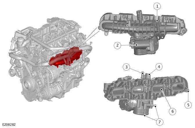
OIL FILTER AND HOUSING ASSEMBLY
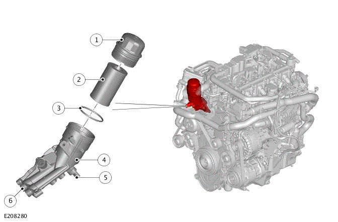
- Cap - Oil filter element
- Oil filter element
- O-ring seal
- Oil filter housing
- Oil pressure and temperature sensor
- Cylinder block connections
The oil filter and housing is a casting which is mounted on the front of the cylinder block. The housing is secured to the cylinder head and the cylinder block with 3 bolts.
The oil filter housing has 3 ports which connect with corresponding ports on the cylinder block. The 2 ports provide the oil pressure inlet and outlet connections and are sealed with floating tube seals. The third port is for the service oil drain when the oil filter element is replaced.
A replaceable cartridge oil filter element is located in the oil filter housing. A plastic cap seals the oil filter element to the oil filter housing. The oil filter element is equipped with an integral bypass valve. If the oil filter element becomes contaminated, to the point that oil flow is restricted, the bypass valve opens. The bypass valve allows oil to flow through the oil filter housing to avoid starving the engine of engine oil.
The oil filter housing has a service drain facility. When the cap is unscrewed 3 to 4 turns, a drain hole opens and the engine oil drains into the oil pan. The service drain facility allows the oil filter element to be removed with no oil contamination of the engine or surroundings.
OIL COOLER
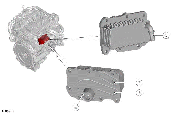
- Engine coolant outlet
- Engine coolant inlet from cylinder block
- Outlet - Engine oil
- Inlet - Engine oil
The engine oil cooler is located on the side of the cylinder block, below the turbocharger. The oil cooler is sealed to the cylinder block with a metal gasket and secured with 7 bolts.
There are 3 ports on the underside of the cooler:
- An engine oil inlet
- An engine oil outlet
- An engine coolant inlet.
There is a port on the other side of the oil cooler for an engine coolant outlet.
The engine oil cooler is an aluminum housing comprising louvered fins and plates. The plates allow a cross flow of engine oil and engine coolant through the cooler but keep the 2 fluids separate. The plates are immersed in engine coolant from the variable coolant pump. The variable coolant pump provides cooling of the engine oil by the temperature differential between the engine oil and the engine coolant.
An anti-drain valve is located in the cylinder block and prevents the oil draining from the engine oil cooler when the engine is not running.
PISTON COOLING OIL JETS
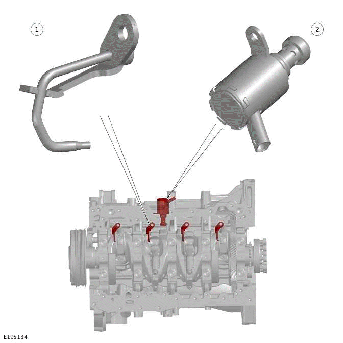
- Piston cooling oil jet (quantity 4)
- Piston cooling oil jet solenoid
The 4 piston cooling oil jets are located in the cylinder block. Each piston cooling oil jet is located adjacent to a cylinder and secured in the cylinder block with a bolt.
The piston cooling oil jets provide piston and gudgeon pin cooling and lubrication. Each piston cooling jet has a single outlet nozzle which sprays oil onto the piston undercrown. The jets are supplied pressurized engine oil from the variable flow oil pump with integral vacuum pump through a drilling in the cylinder block. The oil supply to the drilling is controlled by a piston cooling oil jets solenoid that is controlled by the PCM. The piston cooling oil jet solenoid can open and close the oil supply depending on engine speed and load.
In addition to supplying oil to the piston cooling bore the oil lubricates the small end bearing and the gudgeon pin.
INTAKE MANIFOLD
- Manifold Absolute Pressure and Temperature sensor (MAPT)
- Electric throttle
- Evaporative emission connection
- Engine breather connection
- Bolt (quantity 7)
- Seal (quantity 4)
- Cooling system connections - Electric throttle
The intake manifold is a plastic injection molded assembly, made from 2 shells vibration welded together. The intake manifold is mounted directly to the cylinder head with 7 bolts and sealed with 4 flexible seals.
The main function of the intake manifold is to evenly distribute intake air into the combustion chamber of each cylinder.
A MAPT is located on the top of the intake manifold and secured by a screw. The MAPT is used by the PCM to calculate air density and temperature and determine the engine's air mass flow rate.
The electric throttle is attached to the intake manifold with 4 screws. A gasket seals the joint between the electric throttle and the intake manifold.
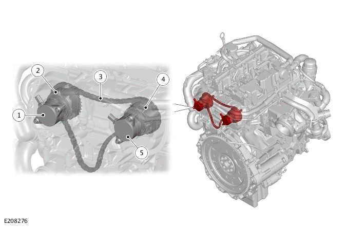
ACTIVE ENGINE MOUNT SYSTEM
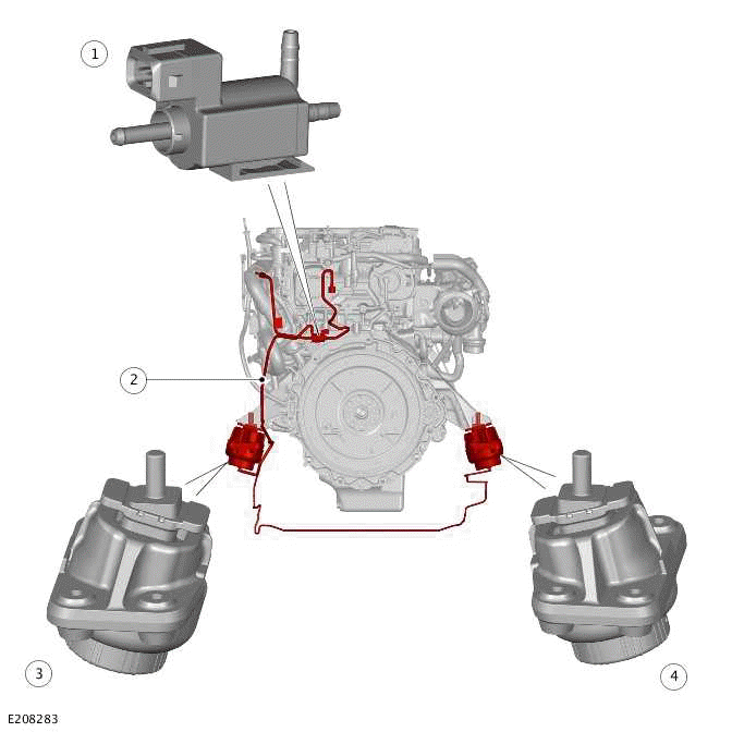
- Active engine mount solenoid
- Vacuum pipe
- Active engine mount - Left
- Active engine mount - Right
The active engine mount system comprises:
- 2 active engine mounts
- Active engine mount solenoid
- Connecting vacuum pipes.
The PCM controls the vacuum operated engine mounts through an active engine mount solenoid. If the active engine mount solenoid is activated the active engine mounts became soft. The active engine mounts operate at idle speed, and are switched off when the engine speed goes above a predetermined threshold. The active engine mounts are switched off when the engine speed increases to 1,250 RPM.
NOISE, VIBRATION AND HARSHNESS PADS
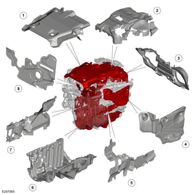
- NVH pad - Cylinder head top
- NVH pad - Continuously Variable Valve Lift (CVVL) assembly
- NVH pad - Cylinder head rear
- NVH pad - Intake manifold
- NVH pad - Cylinder block left
- NVH pad - Oil pan
- NVH pad - Cylinder block right
- NVH pad - Front upper
The NVH pads are attached to the Ingenium I4 2.0L petrol engine in order to reduce NVH experienced by the driver or passenger(s). The pads are made of either a pur foam or a multi layer mixed fiber and resin laminate composite depending on application.
The NVH package consists the following:
- 2 NVH pads for each side of the cylinder block.
- 2 NVH pads on the top of the cylinder head.
- A NVH pad at the front of the cylinder head.
- A NVH pad over the upper timing chain cover.
- A NVH pad for the oil pan.
READ NEXT:
 Engine - Diagnosis and Testing
DIAGNOSIS AND TESTING
INSPECTION, VERIFICATION AND ADDITIONAL WARNINGS FOR ELECTRIC VEHICLES
WARNINGS:
A risk assessment must be performed before any work is undertaken.
Failure to comply with thi
Engine Oil Vacuum Draining and Filling
GENERAL PROCEDURES
SPECIAL TOOL(S)
JLR-303-1644
Oil Extraction Kit
PART(S)
DRAINING
WARNINGS:
The spilling of hot oil is unavoidable during this procedure, care
must be taken to prevent scalding
Crankshaft Pulley - Ingenium I4 2.0l Petrol
REMOVAL AND INSTALLATION
SPECIAL TOOL(S)
JLR-303-1628
Remover/Installer, Front Crankshaft Seal
JLR-303-1630
Locking Tool, Crankshaft Pulley
PART(S)
REMOVAL
NOTE:
This procedure contains some vari
SEE MORE:
Engine Front Cover - Ingenium I4 2.0l Petrol
REMOVAL AND INSTALLATION
SPECIAL TOOL(S)
303-1433
Lower Timing Cover Alignment tool
JLR-303-1628
Remover/Installer, Front Crankshaft Seal
PART(S)
REMOVAL
NOTE:
This procedure contains some variation in the illustrations depending
on the vehicle specification, but the
essential information is
'A' Frame Protection Bar
'A' FRAME PROTECTION BAR - PART NUMBER:
VPLEP0385
REMOVAL AND INSTALLATION
WARNING:
Accessories which are not correctly installed can be dangerous. Read the
instructions carefully prior to
installation. Comply with instructions at all times. If in doubt, contact your
nearest approved retailer.
CAU
