
Land Rover Defender: Engine and Ancillaries - Removal
ENGINE AND ANCILLARIES - INGENIUM I4 2.0L PETROL
REMOVAL
SPECIAL TOOL(S)
.png)
100-012
Slide Hammer
.png)
100-012-01
Slide Hammer Adapter
.png)
JLR-303-1630
Locking Tool, Crankshaft Pulley
.png)
JLR-310-254
Injector Remover
1. Always follow the Petrol and Petrol-Ethanol Fuel Systems Health and Safety Precautions, before any repairs are done to the fuel system.
2. Raise and support the vehicle on a suitable 2 post lift.
3. Disconnect the startup battery ground cable.
4. Remove the engine assembly.
5.
.png)
- Remove the drain plug and allow engine oil to drain into a suitable container.
- Install and tighten the drain plug.
Torque: 23Nm
6.
.png)
- Remove the 3 clips.
- Remove the Noise, Vibration and Harshness (NVH) material.
7.
.png)
- Release the wiring harness clip.
- Remove the 2 bolts.
- Release the 2 engine coolant hose clamps.
- Remove the engine coolant pipe.
8.
.png)
- Disconnect the engine coolant pipe.
- Release the clip.
- Remove the engine coolant pipe.
9.
.png)
- Disconnect the 2 breather pipe connectors.
- Remove the breather pipe.
10.
.png)
- Remove the 2 bolts.
- Disconnect the engine coolant hose.
- Remove the engine coolant hose.
11.
.png)
- Disconnect the vacuum pipe connector.
- Release the 5 vacuum harness clips.
- Remove the vacuum harness.
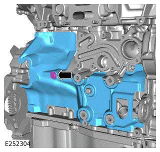
12.
.png)
Remove the 2 bolts.
13.
.png)
- Disconnect the 2 electrical connectors.
- Release the 2 clips.
- Disconnect the breather pipe connector.
- Remove the purge valve assembly.
14.
.png)
- Remove the 3 bolts.
- Release the 2 engine coolant hose clamps.
- Remove the engine coolant hose.
15.
.png)
- Release the engine coolant hose clamp.
- Disconnect the engine coolant hose.
- Remove the 3 bolts.
- Remove the engine coolant hose assembly.
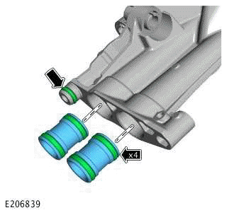
- Inspect the O-ring seal. Remove and discard the O-ring seal if damaged or worn.
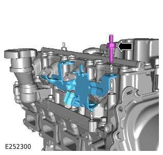
16.
.png)
- Release the engine coolant hose clamp.
- Release the clip.
- Remove the bolt.
- Remove the engine coolant hose.
- Inspect the O-ring seal. Remove and discard the O-ring seal if damaged or worn.
17.
.png)
- Release the engine coolant hose clamp.
- Remove the engine coolant hose.
- Inspect the O-ring seal. Remove and discard the O-ring seal if damaged or worn.
18.
.png)
- Remove the 2 bolts.
- Remove the engine coolant degas separator.
19.
.png)
- Release the 3 wiring harnesses clips.
- Remove the bolt.
- Remove the oil level gauge assembly.
- Remove and discard the O-ring seal.
20.
.png)
- Remove the 2 covers.
- Release the 2 bolts.
- Remove the 2 pulleys.
21.
.png)
- Release the clamp.
- Remove the pipe.
22.
.png)
- Reposition the cover to get access to the nut.
- Remove the nut and disconnect the startup battery cable.
- Disconnect the electrical connector.
- Release the wiring harness clip.
23.
.png)
- Remove the 2 bolts.
- Remove the generator.
24.
.png)
Disconnect the 2 electrical connectors.
25.
.png)
- Disconnect the 4 electrical connectors.
- Remove the 2 bolts.
- Release the 2 wiring harness clips.
26.
.png)
- Disconnect the 2 electrical connectors.
- Remove the 2 bolts.
27.
.png)
- Disconnect the 2 electrical connectors.
- Release the 4 wiring harness clips.
28.
.png)
- Release the wiring harness clip.
- Disconnect the 2 electrical connectors.
29.
.png)
- Disconnect the 3 electrical connectors.
- Release the 4 wiring harness clips.
30.
.png)
- Release the 8 wiring harness clips.
- Disconnect the 4 electrical connectors.
31.
.png)
- Remove the 2 nuts.
- Release the 3 wiring harness clips.
- Remove the bolt.
- Disconnect the 11 electrical connectors.
32.
.png)
- Disconnect the 2 electrical connectors.
- Release the 2 wiring harness clips.
33.
.png)
Remove the wiring harness.
34.
.png)
- Remove the 3 bolts.
- Release the 2 wiring harnesses clips.
- Remove the wiring harness.
35.
NOTE: If required, use a suitable tool to prevent the pulley from rotating.
.png)
- Remove the 3 bolts.
- Remove the engine coolant pump pulley.
36.
.png)
- Remove the 6 bolts.
- Remove the coolant pump.
- Inspect the gasket. If the gasket is damaged or worn, a new engine coolant pump must be installed.
37.
.png)
- Remove the 4 bolts.
- Remove the bracket.
38.
.png)
- Release the 2 banjo bolts.
- Remove the turbocharger oil supply pipe.
39.
.png)
- Cut and remove the 2 lower sealing washers.
- Remove and discard the 2 banjo bolts.
- Remove and discard the 4 sealing washers.
40.
.png)
- Remove the 4 bolts.
- Remove the heatshield.
41.
.png)
- Remove the bolt (1).
- Remove the and discard the bolt (2).
- Remove the heatshield.
42.
.png)
- Remove the bolt.
- Remove the heatshield.
43.
.png)
- Remove the bolt.
- Remove the turbocharger oil return pipe.
- Remove and discard the 2 O-ring seals.
44.
.png)
- Remove and discard the 4 nuts.
- Remove the turbocharger.
45.
.png)
Remove and discard the exhaust manifold gasket.
46.
.png)
- Disconnect the 2 engine coolant hose clamps.
- Remove the engine coolant hose.
47.
.png)
- Remove the 7 bolts.
- Remove the engine oil cooler.
- Remove and discard the gasket.
48.
.png)
- Remove the 2 bolts.
- Remove the engine coolant pipe.
- Inspect the O-ring seal. Remove and discard the O-ring seal if damaged or worn.
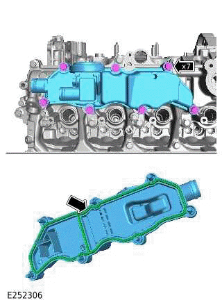
49.
NOTE: The bolts will remain captive.
.png)
- Release the engine coolant hose clamp and disconnect the engine coolant hose.
- Release the 7 bolts.
- Remove the intake manifold.
- Remove and discard the 4 O-ring seals.
50.
.png)
- Remove the 4 bolts.
- Remove the thermostat housing.
- Inspect the gasket. Remove and discard the gasket if damaged or worn.
51.
.png)
- Remove the 4 bolts.
- Remove the bracket.
52.
CAUTION: Fuel lines may be used a maximum of 4 times, paint mark fuel line after each full tightening sequence.
.png)
- Release the High Pressure (HP) fuel line union.
- Remove the 2 bolts.
- Remove the HP fuel line.
53.
CAUTION: Fuel lines may be used a maximum of 4 times, paint mark fuel line after each full tightening sequence.
.png)
- Release the 2 HP fuel line unions.
- Remove the HP fuel line.
54.
CAUTION: Loosen each of the bolts 1 turn at a time until the spring tension is fully released.
.png)
- Remove the 2 bolts.
- Remove the HP fuel pump.
- Inspect the O-ring seal. Remove and discard the O-ring seal if damaged or worn.
55.
.png)
Remove the HP fuel pump tappet.
56.
.png)
- Remove the 4 bolts.
- Remove the 4 ignition coils.
57.
.png)
Release the 4 wiring harness clips.
58.
.png)
- Remove the 4 bolts.
- Remove the fuel rail.
59.
.png)
- Disconnect the 4 electrical connectors.
- Remove the wiring harness.
60.
.png)
Remove and discard the 4 fuel injector spring clamps.
61.
.png)
Install the special tool.
Special Tool(s): JLR-310-254
62.
.png)
Use the special tool to remove the fuel injector.
Special Tool(s): 100-012, 100-012-01, JLR-310-254
63.
.png)
Remove and discard the fuel injector O-ring seal and washer.
64.
.png)
Remove and discard the Teflon seal.
65. Repeat steps 61 to 64 for the 3 remaining fuel injectors.
66.
.png)
- Remove the 2 bolts.
- Remove the 2 Camshaft Position Sensor (CMP) sensors.
- Inspect the 2 O-ring seals. Remove and discard the O-ring seals if damaged or worn.
67.
.png)
- Remove the 4 bolts.
- Remove the 2 variable valve timing (VVT) solenoids.
- Inspect the 2 O-ring seals. Remove and discard the O-ring seals if damaged or worn.
68.
CAUTION: Note the installed position of the component(s) prior to removal.
.png)
- Remove the bolt.
- Remove the knock sensor.
69.
CAUTION: Note the installed position of the component(s) prior to removal.
.png)
- Remove the bolt.
- Remove the knock sensor.
70.
NOTE: If equipped.
.png)
- Remove the cylinder block heater.
- Remove and discard the gasket.
71.
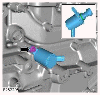
- Remove the bolt.
- Remove the piston cooling oil jet solenoid.
- Inspect the O-ring seal. Remove and discard the O-ring seal if damaged or worn.
72.
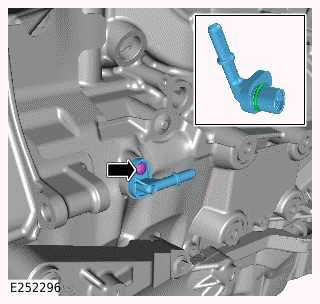
- Remove the bolt.
- Remove the vacuum pipe connector.
- Inspect the O-ring seal. Remove and discard the O-ring seal if damaged or worn.
73.
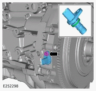
- Remove the bolt.
- Remove the Crankshaft Position Sensor (CKP) sensor.
- Inspect the O-ring seal. Remove and discard the O-ring seal if damaged or worn.
74.
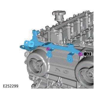
- Remove the 2 bolts.
- Remove the bracket.
75.
- Remove the bracket.
- Remove the bolt.
76.
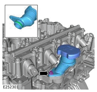
- Remove the bolt.
- Remove the oil filler.
- Inspect the O-ring seal. Remove and discard the O-ring seal if damaged or worn.
77.
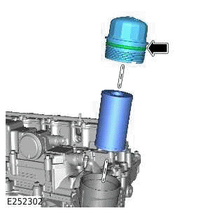
- Remove the oil filter element cap.
- Remove and discard the oil filter element.
- Remove and discard the O-ring seal.
78.
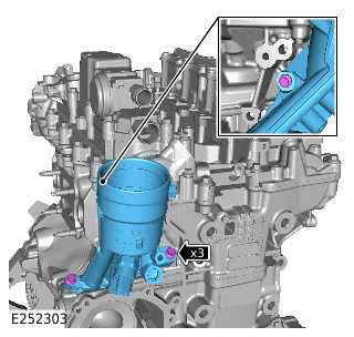
- Remove the 3 bolts.
- Remove the oil filter housing.
79.
Remove and discard the 5 O-ring seals.
80.
NOTE: The bolts will remain captive.
- Release the 7 bolts.
- Remove the engine vent oil separator.
- Remove and discard the gasket.
81.
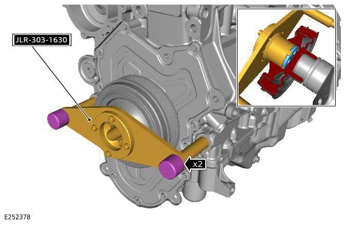
Install the special tools.
Special Tool(s): JLR-303-1630
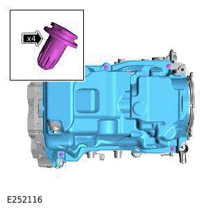
82.
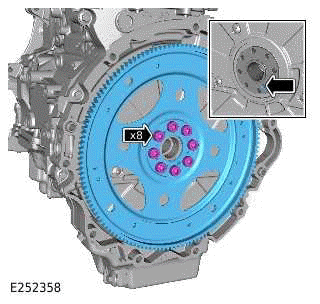
- Remove and discard the 8 bolts.
- Remove the drive plate.
83.
CAUTION: The bolts can only be used a maximum of 4 times. Mark the bolts with a center punch. If 3 punch marks are visible, discard the bolts.
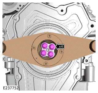
Remove the 4 bolts.
84.
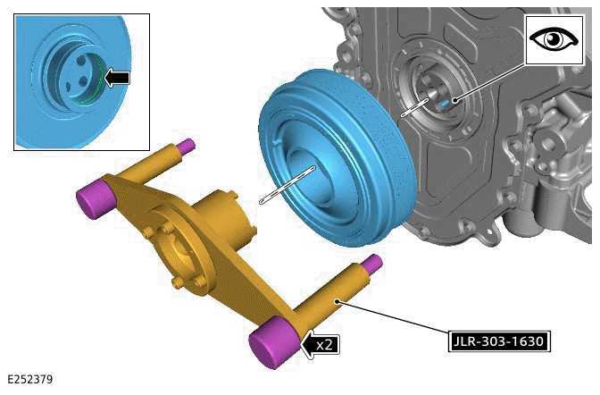
- Remove the special tools.
Special Tool(s): JLR-303-1630
- Remove the crankshaft pulley.
- Inspect the O-ring seal. Remove and discard the O-ring seal if damaged or worn.
85.
- Remove the 4 clips.
- Remove the NVH material.
86.
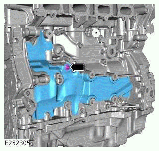
- Remove the clip.
- Remove the NVH material.
87.
- Remove the bolt.
- Remove the NVH material.
READ NEXT:
 Engine - Installation
ENGINE - INGENIUM I4 2.0L PETROL/INGENIUM I4 2.0L PETROL - PHEV
INSTALLATION
SPECIAL TOOL(S)
JLR-303-1633-01
Engine Lifting Kit
JLR-303-1673
Engine stand adaptor
GENERAL EQUIPMENT
PART(S)
WARNING:
Engine and Ancillaries - Installation
ENGINE AND ANCILLARIES - INGENIUM I4 2.0L PETROL
INSTALLATION
SPECIAL TOOL(S)
303-680
Socket, Cylinder Head Temperature Sensor
310-198
Installer, Teflon Seal
JLR-303-1630
Locking Tool, Crankshaft P
Exhaust System
Exhaust System - Ingenium I4 2.0l Petrol/Ingenium I4 2.0l Petrol - PHEV
SPECIFICATIONS
NOTE:
Numbers with a green background are a single use component.
COMPONENT TORQUE LOCATION
COMPONENT TORQUE LO
SEE MORE:
Mobile Phone - Description
MOBILE PHONE SYSTEM
The mobile phone system uses:
IGM / ICCM
FCDIM
Microphone
Left steering wheel switch
AAM
Bluetooth/WiFi antenna.
The mobile phone system has a number of features:
Conference calling.
Usability and information online with mobile phones.
Sort numbers from a range of pop
Steering and Wheel Alignment
Vehicles with steering wheel angles within +/-3 degrees to the horizontal as
shown in illustration E257061 should not
be adjusted as they meet Jaguar Land Rover specifications.
NOTE:
Dependent on specification the relationship between the steering wheel control
switches / paddle shifts /
steering
