
Land Rover Defender: Component Location, Overview
COMPONENT LOCATION
COMPONENT LOCATION - EXTERNAL VIEW
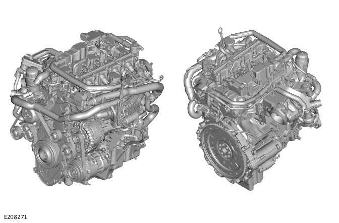
OVERVIEW
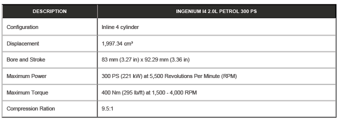
The Ingenium I4 2.0L petrol engine is an inline 4 cylinder, turbocharged engine that employs advanced modular design principles.
The engine features a split cooling system. The system contains a Powertrain Control Module (PCM) controlled electric thermostat and a fully variable coolant pump. The variable coolant pump enables engine coolant to remain static in the engine to maximize heat transfer during warm up. When engine coolant flow is required for engine cooling, the minimum flow is provided by the variable coolant pump.
The split cooling electric thermostat housing limits coolant flow in the cylinder block while allowing engine coolant to circulate through cross flow channels in the cylinder head. Parasitic losses are also optimized when the variable coolant pump is delivering reduced flow.
An electronically controlled variable flow oil pump with integral vacuum pump matches its flow rate according to engine speed, load and temperature. Oil flow to the piston cooling oil jets is solenoid controlled and operates only when needed.
The 2 camshafts incorporate the Variable Camshaft Timing (VCT) system. The VCT system allows the timing of the intake and exhaust valves to be adjusted independently of each other. The VCT system is controlled by the PCM using information from the Camshaft Position Sensor (CMP).
Beside the VCT there is a Continuously Variable Valve Lift (CVVL) system that can adjust the intake valve timing and maximum lift. The CVVL system allows the engine to always operate at optimal efficiency. The CVVL system reduces fuel consumption and increases power and torque in the lower speed range. The CVVL system is controlled by the PCM.
The engine uses a Bosch High Pressure (HP) Direct Injection (DI) fuel system. The fuel pressure is provided by a HP fuel pump which is driven from the exhaust camshaft. The HP fuel pump supplies the fuel rail, and then the fuel rail supplies the 4 fuel injectors with fuel at a controlled pressure.
There are many dynamic and static seals on the engine. All seals and gaskets shall be considered single use and if they are removed shall be replaced.
Various engine systems are located on the engine assembly and driven directly and indirectly by the engine operation.
Refer to the relevant section for further information:
- Engine cooling
- Fuel system
- Air intake system
- Engine emission control
- Accessory drive
- Starting system
- Turbocharger
Technical Specifications
READ NEXT:
 Description
CYLINDER BLOCK COMPONENTS
Bolt - Cylinder block front cover (quantity 14)
Cylinder block front cover
Cylinder block
Cylinder block rear cover and oil seal
Bolt - Cylinder block rear cover and o
Engine - Diagnosis and Testing
DIAGNOSIS AND TESTING
INSPECTION, VERIFICATION AND ADDITIONAL WARNINGS FOR ELECTRIC VEHICLES
WARNINGS:
A risk assessment must be performed before any work is undertaken.
Failure to comply with thi
Engine Oil Vacuum Draining and Filling
GENERAL PROCEDURES
SPECIAL TOOL(S)
JLR-303-1644
Oil Extraction Kit
PART(S)
DRAINING
WARNINGS:
The spilling of hot oil is unavoidable during this procedure, care
must be taken to prevent scalding
SEE MORE:
Heater Core
REMOVAL AND INSTALLATION
PART(S)
REMOVAL
NOTE:
This procedure contains illustrations showing certain components
removed to provide extra clarity.
This procedure contains some variation in the illustrations depending
on the vehicle specification, but the
essential information is always corre
Transmission Fluid Level Check
GENERAL PROCEDURES
SPECIAL TOOL(S)
307-452
Wrench, Transmission Filler Plug
GENERAL EQUIPMENT
PART(S)
CHECK
WARNING:
Observe due care when working near a hot exhaust system.
Observe due care when draining, as the fluid can be very hot.
NOTE:
This procedure contains some variation in the ill
