
Land Rover Defender: Intake Manifold - Ingenium I4 2.0l Petrol
REMOVAL AND INSTALLATION
PART(S)
.png)
REMOVAL
CAUTION: Before disconnecting any components, make sure the area is clean and free from foreign material. When disconnected all openings must be sealed.
NOTE:
- This procedure contains some variation in the illustrations depending on the vehicle specification, but the essential information is always correct.
- This procedure contains illustrations showing certain components removed to provide extra clarity.
1. Raise and support the vehicle on a suitable 2 post lift.
2. Disconnect the startup battery ground cable.
3. Partially drain the cooling system.
4. Remove the engine cover.
5. Remove the secondary bulkhead center panel.
6.
WARNING: Be prepared to collect escaping fuel.
.png)
- Release the 2 clips.
- Release the 2 fuel line clips.
- Disconnect the 2 fuel lines.
7.
.png)
- Release the 3 fasteners.
- Remove the Noise, Vibration and Harshness (NVH) material.
8.
.png)
- Disconnect the breather pipe from the engine vent oil separator.
- Disconnect the breather pipe from the intake manifold.
- Remove the breather pipe.
9.
CAUTION: Be prepared to collect escaping coolant.
.png)
- Release the coolant hose clip.
- Disconnect the coolant hose.
- Reposition the coolant hose away from the intake manifold.
10.
.png)
- Remove the 2 bolts.
- Release the clamp.
- Disconnect the coolant pipe from the coolant hose.
- Remove the coolant pipe.
11.
.png)
- Release the coolant hose clip.
- Disconnect the coolant hose from the thermostat housing.
- Remove the coolant hose.
12.
.png)
- Disconnect the fuel vapor pipe from the charge air cooler outlet pipe.
- Release the 2 clips.
- Disconnect the fuel vapor pipe from the intake manifold.
- Disconnect the fuel vapor pipe from the purge valve.
- Release the clip.
- Disconnect the electrical connector from the purge valve.
- Release the purge valve from the clip.
- Remove the purge valve assembly.
13.
.png)
- Release the clip.
- Reposition the vacuum pipe away from the intake manifold.
14.
CAUTION: Be prepared to collect escaping coolant.
.png)
- Remove the 3 bolts.
- Release the 3 clamps.
- Disconnect the 3 coolant hoses from the coolant pipe.
- Remove the coolant pipe.
15.
.png)
- Disconnect the electrical connector from the Manifold Absolute Pressure and Temperature sensor (MAPT) sensor.
- Disconnect the electrical connector from the knock sensor.
- Release the clip.
- Release the wiring harness from the clip.
16.
.png)
- Disconnect the electrical connector from the throttle body.
- Release the clip.
17.
.png)
- Release the clamp.
- Disconnect the charge air cooler outlet pipe from the throttle body.
18.
.png)
Remove the bolt.
19.
CAUTION: Be prepared to collect escaping coolant.
.png)
- Release the clamp.
- Disconnect the coolant hose from the thermostat housing.
20.
NOTE: The 6 intake manifold bolts are captive.
.png)
- Loosen the 6 bolts.
- Remove the highlighted bolt.
- Remove the intake manifold.
21.
NOTE: Do not disassemble further if the component is removed for access only.
.png)
Remove and discard the 4 seals.
22.
NOTE: This step is not required if the component is removed for access only.
.png)
- Remove the bolt.
- Remove the MAPT sensor.
23.
NOTE: This step is not required if the component is removed for access only.
.png)
- Remove the 4 bolts.
- Remove the throttle body.
- Remove and discard the gasket.
INSTALLATION
1.
NOTE: This step is not required if the component is removed for access only.
.png)
- Install a new throttle body gasket.
Renew Part: Throttle body gasket Quantity: 1.
- Install the throttle body.
- Install and tighten the 4 bolts in the illustrated sequence.
Torque: 12Nm
2.
NOTE: This step is not required if the component is removed for access only.
- Install the MAPT sensor.
- Install and tighten the bolt.
Torque: 5Nm
3.
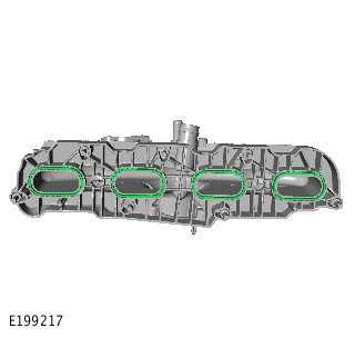
Install 4 new intake manifold seals.
Renew Part: Intake manifold seals Quantity: 4.
4.
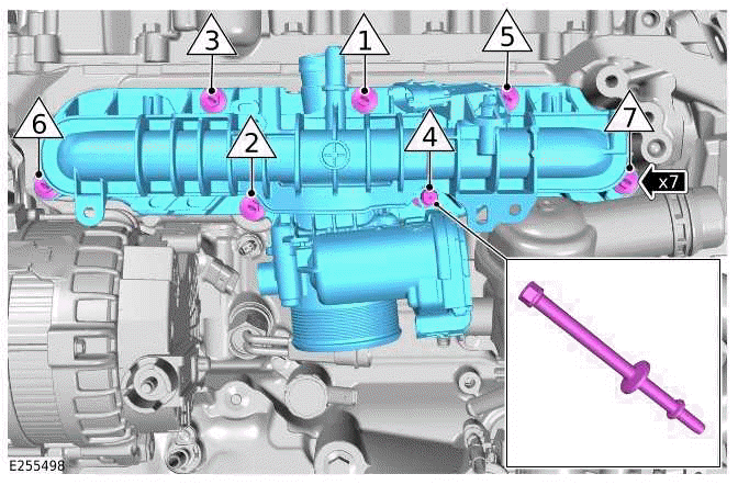
- Install the intake manifold.
- Install, but do not fully tighten the highlighted bolt.
- Tighten the 7 bolts.
Torque: 12Nm
5.
- Connect the coolant hose to the thermostat housing.
- Install the clamp.
6.
- Reposition the oil level gauge in the correct location.
- Install and tighten the bolt.
Torque: 8Nm
7. Connect the charge air cooler outlet pipe to the throttle body.
8.
- Connect the electrical connector to the throttle body.
- Install the clip.
9.
- Connect the electrical connector to the MAPT sensor.
- Connect the electrical connector to the knock sensor.
- Install the 2 clips.
10.
- Install the coolant pipe.
- Install and tighten the 3 bolts.
Torque: 10Nm
- Connect the 3 coolant hoses to the coolant pipe.
- Install the 3 clamps.
11.
- Reposition the vacuum pipe into the correct location.
- Install the clip.
12.
- Install the purge valve assembly.
- Connect the fuel vapor pipe to the intake manifold.
- Connect the fuel vapor pipe to the charge air cooler outlet pipe.
- Connect the fuel vapor pipe to the purge valve.
- Install the 2 clips.
- Connect the electrical connector to the purge valve.
13.
- Install the coolant hose.
- Connect the coolant hose to the thermostat housing.
14.
- Install the coolant pipe.
- Install and tighten the 2 bolts.
Torque: 10Nm
- Connect the coolant hose to the coolant pipe.
- Install the clamp.
15.
- Connect the coolant hose to the coolant pipe.
- Install the coolant pipe clip.
16.
- Install the breather pipe.
- Connect the breather pipe to the intake manifold.
- Connect the breather pipe to the engine vent oil separator.
17.
- Install the NVH material.
- Install the 3 fasteners.
18. Connect the 2 fuel lines.
19. Install the secondary bulkhead center panel.
20. Install the engine cover.
21. Vacuum fill the cooling system.
22. Connect the startup battery ground cable.
READ NEXT:
 Upper Timing Cover
REMOVAL AND INSTALLATION
PART(S)
REMOVAL
WARNING:
Be prepared to collect escaping coolant.
CAUTION:
Before disconnecting any components, make sure the area is clean and free from
foreign material. W
Lower Timing Chain - Ingenium I4 2.0l Petrol
REMOVAL AND INSTALLATION
SPECIAL TOOL(S)
JLR-303-1630
Locking Tool, Crankshaft Pulley
JLR-303-1635
Camshaft Setting Tool
JLR-303-1636
Locking Tool, Variable Camshaft Timing Actuator /
Unit
JLR-303
Oil Filter Housing
REMOVAL AND INSTALLATION
PART(S)
REMOVAL
WARNING:
The spilling of hot engine oil is unavoidable during this procedure, care must
be taken to prevent scalding.
NOTE:
This procedure contains some va
SEE MORE:
Rear Spoiler
REMOVAL AND INSTALLATION
REMOVAL
NOTE:
This procedure contains some variation in the illustrations depending
on the vehicle specification, but the
essential information is always correct.
This procedure contains illustrations showing certain components
removed to provide extra clarity.
1.
Brake Caliper - Vehicles With: 350mm Brake Disc
REMOVAL AND INSTALLATION
GENERAL EQUIPMENT
PART(S)
REMOVAL
CAUTION:
Before the disconnection or removal of any components, make sure the area around
joint faces and
connections are clean. Plug any open connections to prevent contamination.
NOTES:
This procedure contains illustrations showing ce
