
Land Rover Defender: Cabin Comfort Climate Control System
DIAGNOSIS AND TESTING
PRINCIPLES OF OPERATION
For a detailed description of the Climate Control System, refer to the relevant Description and Operation section in the workshop manual.
Air Distribution and Filtering (Description and Operation), Heating and Ventilation (Description and Operation), Air Conditioning (Description and Operation), Control Components (Description and Operation).
INSPECTION AND VERIFICATION
WARNING: Servicing must be completed by personnel familiar with both vehicle system and the charging and testing equipment. All operations must be completed in a well ventilated area away from open flame and heat sources.
CAUTION: Diagnosis by substitution from a donor vehicle is NOT acceptable. Substitution of control modules does not guarantee confirmation of a fault, and may also cause additional faults in the vehicle being tested and/or the donor vehicle.
NOTES:
- If a control module or a component at fault and the vehicle remains under manufacturer warranty, refer to the Warranty Policy and Procedures manual, or determine if any prior approval program is in operation, prior to the installation of a new module/component.
- When performing voltage or resistance tests, always use a digital multimeter that has the resolution ability to view 3 decimal places. For example, on the 2 volts range can measure 1mV or 2 K Ohm range can measure 1 Ohm. When testing resistance always take the resistance of the digital multimeter leads into account.
- Check and rectify basic faults before beginning diagnostic routines involving pinpoint tests.
- Verify the customer concern
- Visually inspect for obvious signs of damage and system integrity
Visual Inspection
- If an obvious cause for an observed or reported concern is found, correct the cause (if possible) before proceeding to the next step
- If the cause is not visually evident, verify the symptom and refer to the Symptom Chart, alternatively check for Diagnostic Trouble Code(s) and refer to the Diagnostic Trouble Code(s) (DTC) Index
- Check the JLR claims submission system for open campaigns. Refer to the corresponding bulletins and SSMs which may be valid for the specific customer complaint and complete the recommendations as required
HVAC CONTROL SYSTEM SENSOR RESISTANCE VALUES
SYMPTOM CHART - AUTO CLIMATE CONTROL

SYMPTOM CHART - MANUAL CLIMATE CONTROL
PINPOINT TESTS
PINPOINT TEST A : PASSENGER COMPARTMENT TEMPERATURE SENSOR CHECKS
PINPOINT TESTS
PINPOINT TEST B : DUCT AIR TEMPERATURE SENSOR CHECKS
PINPOINT TESTS
PINPOINT TEST C : RECIRCULATION INLET DOOR POSITION
PINPOINT TEST C : RECIRCULATION INLET DOOR POSITION
FRONT TO REAR HVAC SYSTEM VENT IMBALANCE TEST
Diagnostic Procedure
Vent temperature difference test
NOTES:
- If the customer cannot set a constant comfortable temperature and the air blowing through the rear air vents is noticeably hotter than air blowing through other vents, continue with this diagnostic procedure
- DO NOT place the temperature sensor inside the vent as this can give a false reading
- Make sure the vehicle is in a workshop environment and not in direct sunlight
- Start the engine and run the vehicle at idle with all windows and doors closed for 30 minutes to allow the temperature to stabilize
- Set the climate control to MANUAL and FOOT and FACE distribution
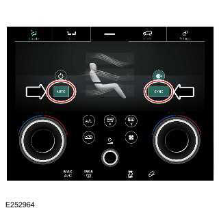
- Confirm the driver and passenger temperatures are set to 22ºC
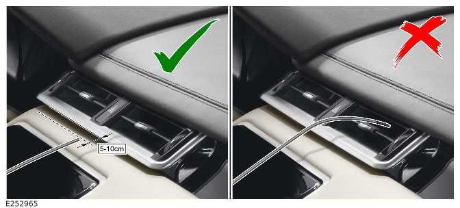
- Place the temperature sensor (Electronic Thermometer RA43230) directly
in front and in the centre (not above
or below), 5-10 cm away from the front centre vent and measure, make a note
of the temperature
- Wait for 60 seconds
NOTE: The temperature probe must be held directly in front and in the centre (not above or below) of the vent 5-10 cm away, incorrect positioning of the probe can cause up to a 4ºC temperature difference
- Place the temperature sensor (Electronic Thermometer RA43230) directly in front and in the centre (not above or below), 5-10 cm away from the rear centre face vent and measure, make a note of the temperature
- If the temperature difference is between 10ºC and 14ºC refer to the symptom chart and continue with diagnostics
- If the temperature difference is greater than 14ºC, please raise a TA case for further guidance
READ NEXT:
 Climate Control System
DIAGNOSIS AND TESTING
PRINCIPLES OF OPERATION
For a detailed description of the Climate Control System, refer to the
relevant Description and Operation section in the
workshop manual.
Air Conditionin
Air Conditioning Compressor Commissioning
GENERAL PROCEDURES
ACTIVATION
CAUTION:
Failure to follow this instruction may result in damage to the component.
1. Set the ignition to the on position, make sure the Air Conditioning (A/C)
is in the
Climate Control
SPECIFICATIONS
Torque Specifications
COMPONENT TORQUE LOCATION
COMPONENT TORQUE LOCATION
COMPONENT TORQUE LOCATION
COMPONENT TORQUE LOCATION
COMPONENT TORQUE LOCATION
COMPONENT TORQUE LOCATI
SEE MORE:
Valves
REMOVAL AND INSTALLATION
SPECIAL TOOL(S)
303-252
Compressor, Valve Spring
GENERAL EQUIPMENT
PART(S)
REMOVAL
WARNINGS:
If the vehicle has been powered down, do not power up the vehicle
until all the bonding points have been
tested.
It is the responsibility of the Electric Vehicle Senior Auth
Camera system overview
Make sure the relevant safety warnings
and cautions have been read and
understood before operating the
camera features.
The camera system is available in three
modes:
On-road.
Off-road.
Towing.
The camera system consists of four
cameras, located as follows:
One is located in the center of th
