
Land Rover Defender: Seat Backpack
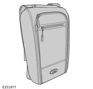
SEAT BACKPACK - PART NUMBER: VPLES0573
REMOVAL AND INSTALLATION
WARNING: Accessories which are not correctly installed can be dangerous. Read the instructions carefully prior to installation. Comply with instructions at all times. If in doubt, contact your nearest approved retailer.
NOTE: This procedure contains some variation in the illustrations depending on the vehicle specification, but the essential information is always correct.
INSTALLATION
1.
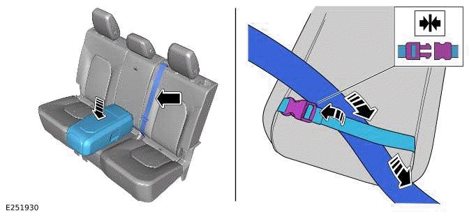
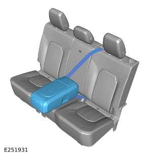
Place the seat backpack in the middle of the second row seats. Strap the seat backpack to the seats by attaching the seat backpack rear strap over the center seatbelt. Engage the second row center seatbelt to the second row center seatbelt buckle.
2.
WARNING: When using the seat backpack on the second row seats the seat backpack must be strapped to the engaged second row center seatbelt.
3.
Unzip the front panel to reveal the main compartment.
4.
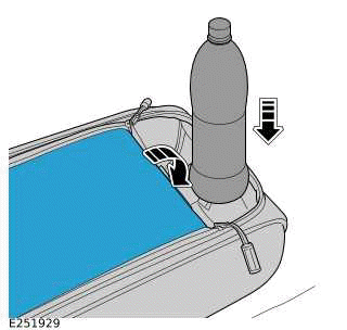
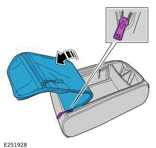
Partially unzip the front panel to use the cup holder section. Tuck the top of the front panel behind the cup holder section.
5.
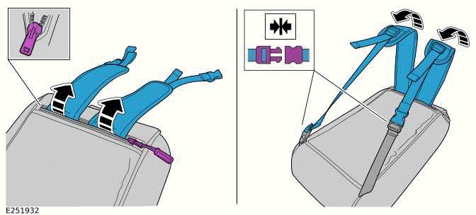
When using the seat backpack outside of the vehicle then follow steps.
- Unzip the top rear section and pull out the shoulder straps.
- Unclip the rear strap and clip each shoulder strap to the adjacent part of the rear strap.
6.
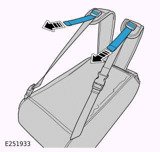
To adjust the straps pull on the part of the strap as illustrated.
READ NEXT:
 Ski Bag
SKI BAG - 110, PART NUMBER: VPLGS0166
REMOVAL AND INSTALLATION
WARNING:
Accessories which are not correctly installed can be dangerous. Read the
instructions carefully prior to
installation. Comply w
Front Treadplates
FRONT TREADPLATES - PART NUMBER: 90:
VPLES0575PVJ, VPLES0595LAA, LR131474,
LR131466, LR131475, LR131467 110: VPLES0576PVJ,
VPLES0596LAA, LR131470, LR141462, LR131471,
LR131463
REMOVAL AND INSTALLATION
Loadspace Treadplate
LOADSPACE TREADPLATE - PART NUMBER:
VPLES0572
REMOVAL AND INSTALLATION
WARNING:
Accessories which are not correctly installed can be dangerous. Read the
instructions carefully prior to
installation.
SEE MORE:
Fuel Tank Draining
GENERAL PROCEDURES
SPECIAL TOOL(S)
310-123
Locking Ring, Fuel Tank
GENERAL EQUIPMENT
PART(S)
DRAINING
WARNING:
Be prepared to collect escaping fuel.
CAUTION:
Before disconnecting any components, make sure the area is clean and free from
foreign material. When
disconnected all openings must be se
Land rover roadside assistance program
LAND ROVER ROADSIDE ASSISTANCE
PROGRAM
As part of Jaguar Land Rover (JLR)'s
commitment to a pleasurable driving
experience, the Land Rover Roadside
Assistance Program is furnished at no
additional cost to you for the term of your
New Vehicle Limited Warranty.
The Land Rover Roadside Assistance
Progr
