
Land Rover Defender: Preliminary Advice, Jacking
PRELIMINARY ADVICE
WARNING: Make sure that the vehicle is stable before completing any work.
CAUTION: Make sure the deployable side steps are set to 'Roof Access' mode (if equipped). Do not jack or lift on the side step mount brackets.
NOTES:
- There is some variation in the illustrations depending on the vehicle specification, but the essential information is always correct.
- Vehicles equipped with air suspension must be set to 'off-road' height when lifted. Return the vehicle to 'normal ride height' when the vehicle is removed from the lift.
The following instructions must be adhered to before raising the vehicle off the ground:
- Position the vehicle on a solid, level surface.
- Apply the Electric Park Brake (EPB).
- Select Park 'P' with the Transmission Control Switch (TCS).
JACKING
VEHICLE JACK
WARNING: Do not work under a vehicle supported only by the vehicle jack, make sure the vehicle is supported with axle stands.
The jack provided with the vehicle is only intended for use in an emergency such as installing the spare wheel at the roadside. DO NOT use the jack for any other purpose. Refer to the Owner's Handbook for the vehicle jack location points and jacking procedures.
HYDRAULIC JACK
WARNING: Make sure that the axle stands are correctly positioned and the vehicle is stable before completing any work.
A hydraulic jack with a minimum lifting capacity of 2000 kg (4,410 lbs) must be used.
FRONT END JACKING
WARNING: Always chock the rear wheels when jacking the front of the vehicle.
CAUTION: Position suitable material between the axle stands and the sill to prevent damage.
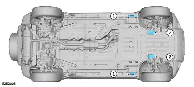
- Sill jacking point
- Front subframe jacking point
To raise the vehicle, jack on the sill jacking points (1).
Position axle stands under the front subframe jacking points (2).
With the vehicle at the desired height, carefully lower the jack until the vehicle rests on the axle stand (2).
Reverse the procedure when removing the vehicle from the axle stands.
REAR END JACKING
WARNING: Always chock the front wheels when jacking the rear of the vehicle.
CAUTION: Position suitable material between the axle stands and the sill to prevent damage.
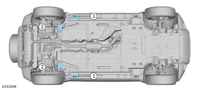
- Sill jacking point
- Rear subframe jacking point
To raise the vehicle, jack on the sill jacking points (1).
Position axle stands under the rear subframe(2).
With the vehicle at the desired height, carefully lower the jack until the vehicle rests on the axle stand (2).
Reverse the procedure when removing the vehicle from the axle stands.
RAISING AND SUPPORTING THE VEHICLE
WARNINGS:
- When jacking the front end first:
- Chock the rear wheels.
- When jacking the rear end first:
- Chock the front wheels.
CAUTION: Position suitable material between the axle stands and the sill to prevent damage.
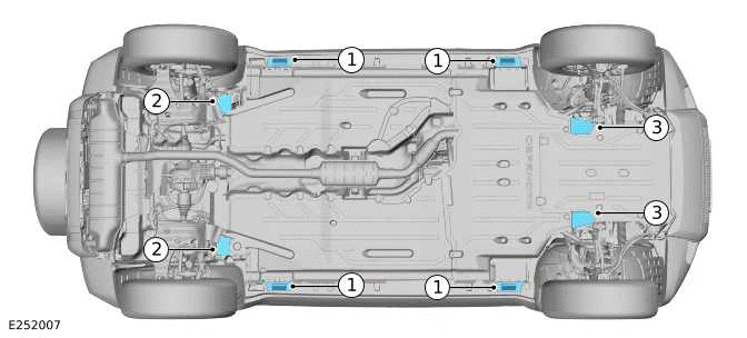
- Sill jacking point
- Rear subframe jacking point
- Front subframe jacking point
To raise the vehicle, jack on the sill jacking points (1).
Position axle stands under the rear subframe (2) or the front subframe jacking points (3).
With the vehicle at the desired height, carefully lower the jack until the vehicle rests on the axle stand (2) and (3).
Reverse the procedure when removing the vehicle from the axle stands.
READ NEXT:
 Lifting
4 POST LIFT
Vehicle On Wheels
WARNING:
If the driveshaft(s)/halfshaft(s) require disconnecting, the vehicle must be
lifted wheel free.
Do not move the vehicle forward and backward on the 4 post lift
Integrated Air Compressor
INTEGRATED AIR COMPRESSOR - PART NUMBER: VPLES0574, VPLES0617
REMOVAL AND INSTALLATION
VPLES0617 (90/110) VPLES0574 (110)
WARNING:
Accessories which are not correctly installed can be dangerous. Read
SEE MORE:
Bolt and Nut Identification
An ISO metric bolt or screw made of steel and larger than 6 mm in diameter
can be identified by either of the symbols
ISO M or M embossed or indented on top of the bolt head.
In addition to marks identifying the manufacturer, the top of the bolt head is
also marked with symbols indicating the
st
Camshaft Carrier
REMOVAL AND INSTALLATION
PART(S)
REMOVAL
NOTE:
This procedure contains some variation in the illustrations depending
on the vehicle specification, but the
essential information is always correct.
This procedure contains illustrations showing certain components
removed to provide extra clari
