
Land Rover Defender: Lifting
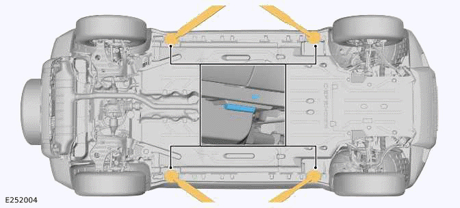
4 POST LIFT
Vehicle On Wheels
WARNING: If the driveshaft(s)/halfshaft(s) require disconnecting, the vehicle must be lifted wheel free.
Do not move the vehicle forward and backward on the 4 post lift to access the fixings.
Position the vehicle on the lift with the front and rear of the vehicle at an equal distance from each end of the ramp.
Chock the wheels and engage the emergency park release lever, apply the EPB.
4 POST LIFT
Wheel Free
WARNING: The vehicle cannot be safely supported in a wheel free condition with longitudinal rails on a 4 post lift, under no circumstances must this method be used.
Transverse hydraulic jacks may be used on a 4 post lift to raise and support the vehicle.
Longitudinal rails MUST NOT be used under any circumstance to raise and support the vehicle.
Where available, a 2 post lift is more suitable and should be used if the vehicle is required to be wheel free.
2 POST LIFT
CAUTION: Place a suitable material between the lift pad and the jacking point to avoid damage to the vehicle.
If the driveshaft(s)/halfshaft(s) require disconnecting, all 4 wheels must be raised off the ground to allow rotation.
With the vehicle raised, it will be necessary to release the EPB.
- Engage the emergency park release lever.
1. Position the vehicle with the center of the lift pillars aligned approximately with the front of the front row seat base cushions.
2. Extend the lifting arms and position the pad under the sill jacking points.
3. Raise the vehicle until the wheels are off the ground and check that the pads of each lifting arm are still correctly positioned.
4. Raise the vehicle to the desired height.
5. Make sure that the vehicle is correctly supported on the lifting pads, that the pads are correctly positioned and are in full contact with the jacking point.
READ NEXT:
 Integrated Air Compressor
INTEGRATED AIR COMPRESSOR - PART NUMBER: VPLES0574, VPLES0617
REMOVAL AND INSTALLATION
VPLES0617 (90/110) VPLES0574 (110)
WARNING:
Accessories which are not correctly installed can be dangerous. Read
Click & Go System Base Unit
CLICK & GO SYSTEM BASE UNIT - PART NUMBER:
VPLRS0388
REMOVAL AND INSTALLATION
WARNINGS:
Accessories which are not correctly installed can be dangerous. Read
the instructions carefully prior t
SEE MORE:
Front Door Tweeter Speaker
REMOVAL AND INSTALLATION
REMOVAL
NOTE:
This procedure contains some variation in the illustrations depending
on the vehicle specification, but the
essential information is always correct.
This procedure contains illustrations showing certain components
removed to provide extra clarity.
This
Optimized land rover assistance
The Optimized Land Rover
Assistance call button is located
in the overhead console, on the
left side.
In the event of a breakdown:
1. Press and release the button's cover.
2. A white LED illuminates in the button.
3. Press the button for 3 seconds to make
a direct call to the Optimized Land
Rover
