
Land Rover Defender: Loadspace Retention Kit - 110
LOADSPACE RETENTION KIT - 110, PART NUMBER: VPLGS0171
REMOVAL AND INSTALLATION
WARNING: Accessories which are not correctly installed can be dangerous. Read the instructions carefully prior to installation. Comply with instructions at all times. If in doubt, contact your nearest approved retailer.
NOTES:
- This procedure contains some variation in the illustrations depending on the vehicle specification, but the essential information is always correct.
- This procedure contains illustrations showing certain components removed to provide extra clarity.
INSTALLATION
1. Open the tailgate.
2. Remove the loadspace cover from the vehicle.
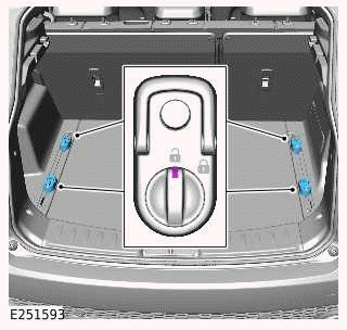
3.
The loadspace retention kit can only be used if the vehicle is equipped with the loadspace rails and the sliding D-loop anchor points.
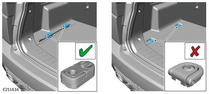
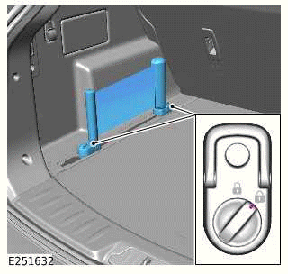
4.
Make sure the sliding D-loop anchor points are unlocked.
5.
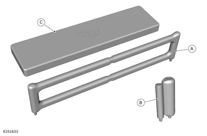
Check which part of the loadspace retention kit is going to be installed into the loadspace.
- If the telescopic loadspace beam (A) will be installed into the loadspace then complete steps 6 to 9.
- If the loadspace band (B) will be installed into the loadspace then start at step 10.
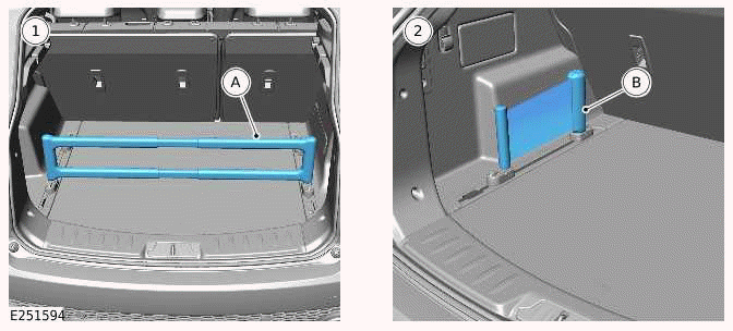
6.
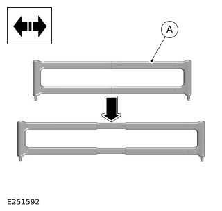
Open the telescopic loadspace beam to the required width.
7.
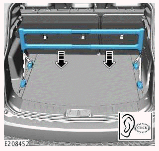
Locate the telescopic loadspace beam into a pair of sliding D-loop anchor points.
8.
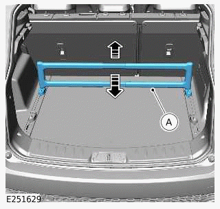
Move the 2 sliding D-loop anchor points and the telescopic loadspace beam they are supporting, to the required position within the loadspace.
9.
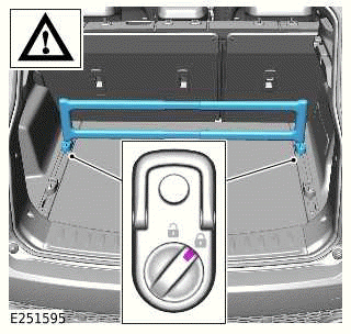
Lock the 2 sliding D-loop anchor points that support the telescopic loadspace beam.
10.
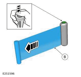
Extend the loadspace band to the required length.
11.
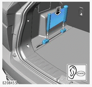
Locate the loadspace band into a pair of sliding D-loop anchor points.
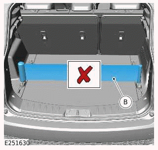
12.
CAUTION: Do not position the loadspace band across the width of the loadspace.
13.
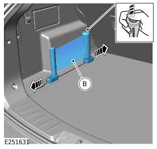
Move the sliding D-loop anchor points and the loadspace band they are supporting, to the required position within the loadspace.
14.
Lock the 2 sliding D-loop anchor points that support the loadspace band.
15.
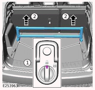
Follow the steps to remove the telescopic loadspace beam.
- Unlock the 2 sliding D-loop anchor points that support the telescopic loadspace beam.
- Lift the telescopic loadspace beam to remove from the sliding D-loop anchor points.
16. Close the tailgate.
17. When not being used, store the telescopic loadspace beam and the loadspace band in the storage bag (C).
READ NEXT:
 Floor Mats
FLOOR MATS - PART NUMBER: 90: VPLES0548,
VPLES0549, VPLES0554, VPLES0555 110:
VPLES0550, VPLES0552, VPLES0551, VPLES0553,
VPLES0556, VPLES0557, VPLES0558, VPLES0559
REMOVAL AND INSTALLATION
WARNING:
A
Seat Backpack
SEAT BACKPACK - PART NUMBER: VPLES0573
REMOVAL AND INSTALLATION
WARNING:
Accessories which are not correctly installed can be dangerous. Read the
instructions carefully prior to
installation. Comply
Ski Bag
SKI BAG - 110, PART NUMBER: VPLGS0166
REMOVAL AND INSTALLATION
WARNING:
Accessories which are not correctly installed can be dangerous. Read the
instructions carefully prior to
installation. Comply w
SEE MORE:
Glass, Frames and Mechanisms
SPECIFICATIONS
Torque Specifications
COMPONENT TORQUE LOCATION
COMPONENT TORQUE LOCATION
COMPONENT TORQUE LOCATION
COMPONENT TORQUE LOCATION
COMPONENT TORQUE LOCATION
COMPONENT TORQUE LOCATION
COMPONENT TORQUE LOCATION
Rear Silencer
REMOVAL AND INSTALLATION
PART(S)
REMOVAL
WARNING:
Observe due care when working near a hot exhaust system.
CAUTION:
Make sure the exhaust system is supported at all times.
NOTE:
This procedure contains illustrations showing certain components
removed to provide extra clarity.
This procedure co
