
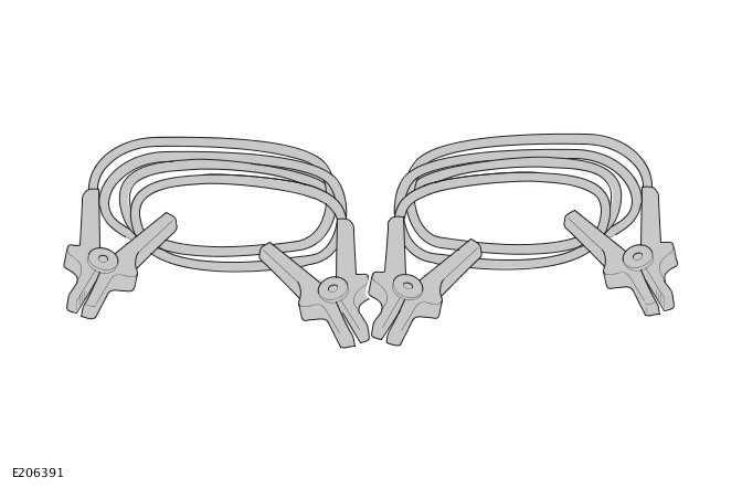
Land Rover Defender: Jump Lead
JUMP LEAD - PART NUMBER: VPLVV0090
REMOVAL AND INSTALLATION
WARNINGS:
- Accessories which are not properly fitted can be dangerous. Read the
instructions carefully prior to fitting.
Comply with instructions at all times. If in doubt, contact your nearest approved retailer.
- Refer to the owners handbook information under 'Vehicle recovery'. Failure to do so may result in vehicle damage and serious injury.
WARNINGS:
- Rotating parts of the engine can cause serious injury. Take extra care when working near rotating parts of the engine.
- Make sure that the parking brake is applied, or suitably chock the wheels. Make sure that Park is selected on an automatic gearbox, or that the manual gearbox is in neutral.
- Always wear appropriate eye protection when working with batteries.
- Never jump start, charge, or try to start a vehicle with a frozen battery. Doing so may result in an explosion.
- During normal use, batteries emit explosive gas sufficient to cause severe explosions - keep sparks and naked lights away from the battery compartment.
- Make sure that there is no physical contact between the slave battery/starting aid and the disabled vehicle other than the jump leads.
- Make sure that the slave battery/starting aid is a 12 volt device.
- Disconnect the jump leads prior to operating any electrical equipment.

Vehicle Jump (Emergency) Starting - Using a Slave Battery/Starting Aid
CAUTIONS:
- Make sure that the correct procedure is followed to meet vehicle specification.
- Before connecting jump leads, make sure that the electrical connections on the disabled vehicle are correct and that all electrical equipment is switched off.

INSTALLATION
WARNING: Carry out the following operations in the sequence given.
Vehicles without Telematics
- Connect the end of the RED (+) jump lead to the POSITIVE (+) jump start terminal of the disabled vehicle.
- Connect the end of the BLACK (-) jump lead to the GROUND (-) jump start terminal of the disabled vehicle.
- Start the engine of the vehicle and allow it to idle.
- Disconnect the BLACK (-) jump lead from the GROUND (-) jump start terminal of the vehicle.
- Disconnect the RED (+) jump lead from the POSITIVE (+) jump start terminal of the vehicle.
INSTALLATION
WARNING: Carry out the following operations in the sequence given.
Vehicles equipped with Telematics
- Make sure the customer has placed stolen vehicle tracking into Service Mode, (if equipped).
- Connect the end of the RED (+) jump lead to the POSITIVE (+) jump start terminal of the disabled vehicle.
- Connect the end of the BLACK (-) jump lead to the GROUND (-) jump start terminal of the disabled vehicle.
- Start the engine of the vehicle and allow it to idle.
- Disconnect the BLACK (-) jump lead from the GROUND (-) jump start terminal of the vehicle.
- Disconnect the RED (+) jump lead from the POSITIVE (+) jump start terminal of the vehicle.
- Request that stolen vehicle tracking is removed from Service Mode, (if equipped).
READ NEXT:
 Snow Chains
SNOW CHAINS - PART NUMBER: VPLEW0140
REMOVAL AND INSTALLATION
WARNING:
Accessories which are not correctly installed can be dangerous. Read the
instructions carefully prior to
installation. Comply wi
SEE MORE:
Front Fender Trim Panel
REMOVAL AND INSTALLATION
REMOVAL
CAUTION:
Make sure to protect the paintwork.
NOTE:
This procedure contains some variation in the illustrations depending
on the vehicle specification, but the
essential information is always correct.
This procedure contains illustrations showing certain compone
Seat belt reminder
Make sure to read and fully understand
the relevant warnings before using any
of the features in this section.
An audible warning sounds, and a warning
lamp illuminates when the following
conditions occur:
The driver seat, or the front seats are
occupied.
The front seat belts have not been
fas
© 2010-2026 Copyright www.lrdefender.org
