
Land Rover Defender: Introduction, How To Use This Workshop Manual
INTRODUCTION
The workshop manual has been written in a format that is designed to meet the needs of technicians worldwide. The objective is to provide descriptions for completing diagnosis and testing, service and repair work with tested and effective techniques, using a common publishing format.
It is structured into groups which are specific to vehicle areas, sections which are component areas, and sub sections which contain lists detailing Specifications, Description and Operation, Diagnosis and Testing, General Procedures, Disassembly and Assembly, Removal and Installation.
HOW TO USE THIS WORKSHOP MANUAL
Appropriate service methods and repair procedures are essential for the safe, reliable operation of all vehicles as well as the personal safety of the individual carrying out the work.
Anyone who does not follow the instructions provided in this manual, must first establish that personal safety or vehicle integrity is not compromised by the choice of method, tools or components.
WARNINGS, CAUTIONS AND NOTES
WARNING: Warnings indicate hazards that may be present while carrying out the procedure. These hazards may cause personal injury if not followed.
CAUTION: Cautions indicate that failure to follow the instruction may result in damage to the vehicle or equipment.
NOTE: Notes provide additional information that is required in the procedure.
General warnings, cautions and notes are included before any procedural steps. These are only used when they apply to each step contained in the procedure.
Step specific warnings, cautions and notes are only assigned to the individual step that they apply to.
POSITIONAL REFERENCES
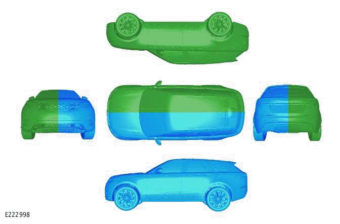
Vehicle
Positional references of the vehicle are always from the drivers seat looking forward.
Left side of the vehicle is shown blue, right side of the vehicle is shown green.
Engine
Positional references of the engine are always from the flywheel, or drive plate, looking towards the crankshaft pulley.
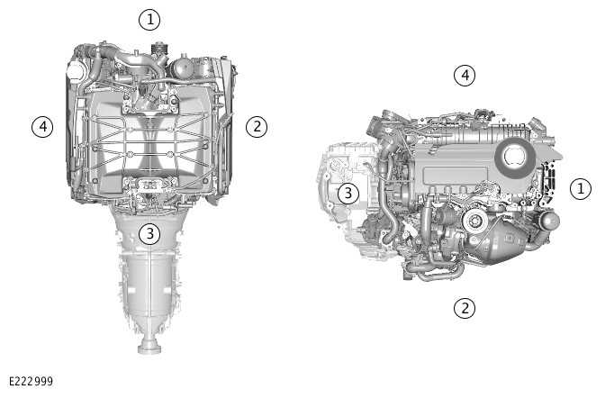
- Front
- Right
- Rear
- Left
PROCEDURE AUTHORING STANDARDS
A storyboard style procedure is the preferred standard used when creating the following types of procedures:
- General Procedures
- Removal
- Installation
- Removal and Installation
The procedures describe the removal and/or installation required to access the serviceable part.
Components or assemblies may be removed and/or installed to access other components or assemblies. In this case, no further disassembly and assembly is required and the procedure steps will have a statement, displayed as a note, providing this information.
Special Tools
If special tools are required to perform the procedure, these will be displayed in a table showing an image of the special tool, the special tool number and a description.
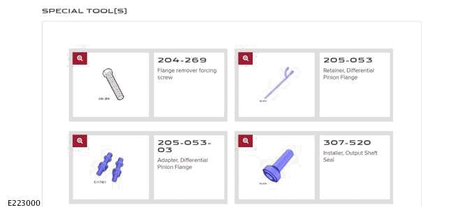
Special tool numbers will also be referenced in all step illustrations where the special tool is visible in the active colour.
Once the tool has been referenced it does will not be replicated in further steps.
General Equipment
If any general equipment is required to perform the procedure, these will be displayed in a table after the special tool table, if applicable, and before any procedural steps. The general equipment table includes all dimensionally specific items, such as drill bits. Tools that are used in an uncharacteristic fashion, particularly hand tools that would not be intuitive to perform the procedure will also be displayed.

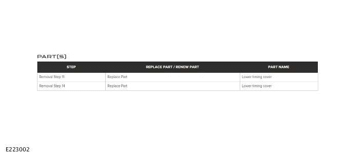
New Parts
If new parts are required in any procedural step, these will be referenced in the parts table. There will be a reference to which step the new part is associated with.
The general equipment table does not include hand tools such as wrenches, pliers and screwdrivers that are used as expected.
Step Types
All steps that include an illustration can have supporting text that contains a primary instruction. The illustrated step can contain supporting sub-steps where further clarification is necessary.
Basic Step - These steps can be supported with a primary instruction.
Bullet Point Step - These is used for steps containing multiple actions/instructions in relation to the same component.
Numbered Sub-Step - These are used when specific order must be followed and are indicated in the illustration.
Numbers within a illustration indicate the order of the steps and align with the supporting text.
Sequence Step - There are used sequences, stages and/or loosening steps are shown in the procedure step. In most cases these will only be required in the installation steps.
PROCEDURE ILLUSTRATION STANDARDS
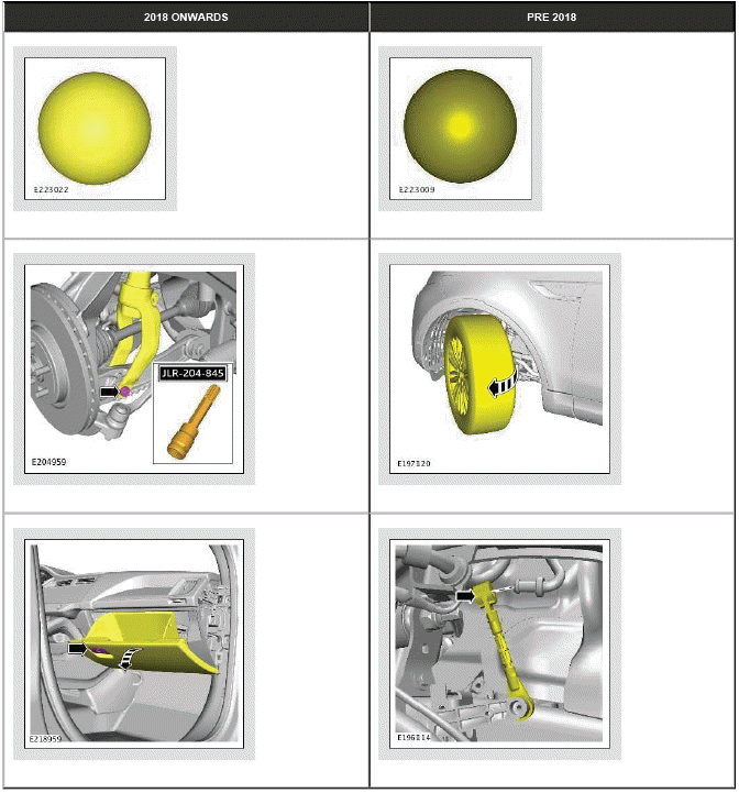
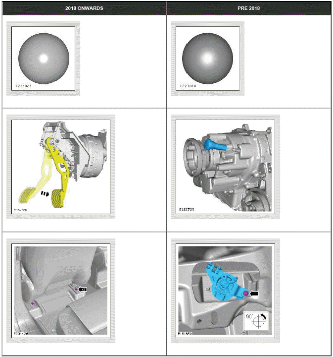
All illustrations will have certain components and/or assemblies shown in specific colors. These colors are used to show different actions to provide further clarity.
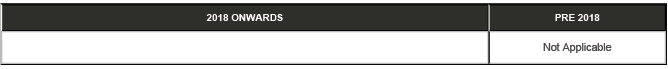
NOTE: At the start of 2018, a new color pallette was introduce to further enhance the workshop manual.
The definition of all the colors used are as follows:
Focus Item - Main
A component to be removed/installed or disassembled/assembled. This color can also be used to highlight a feature /area such as timing or alignment mark, or regions to clean, grease or oil.

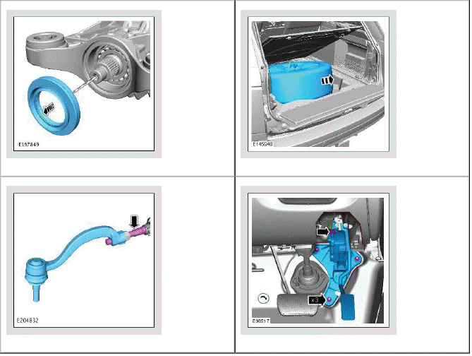
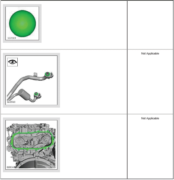
Focus Item - Alternative
An alternative color when multiple parts are to be removed in succession. This color, in addition to focus blue, is clearer to see how many parts are to be removed.

Gaskets and O-Ring Seals
All gaskets and o-ring seals are shown in this color. If they are required to be replaced or inspected this will be detailed in the step.
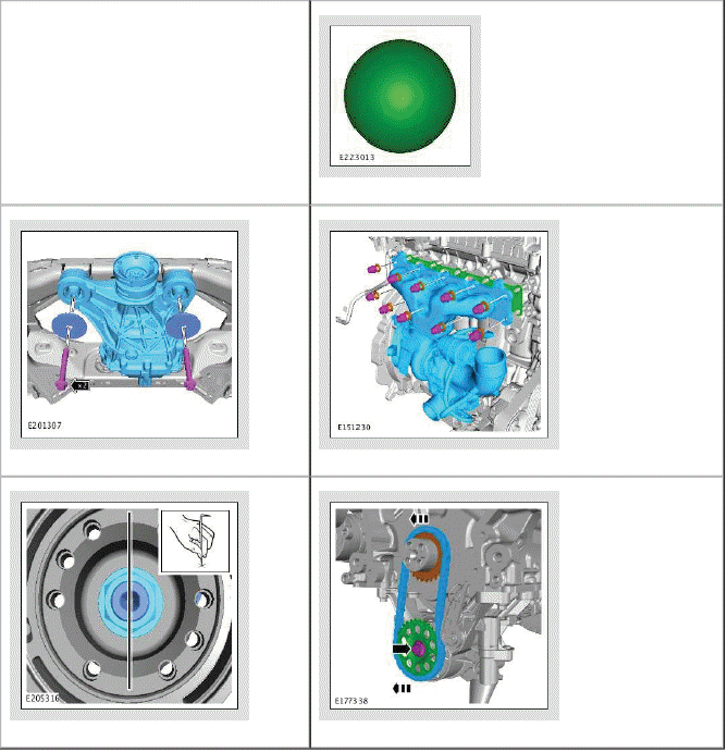
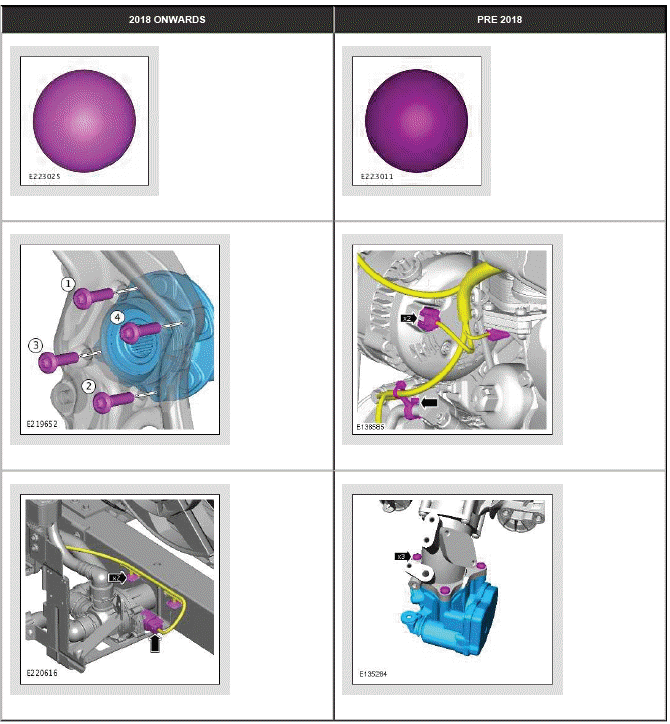
Component Reposition
This color is used on components that are not being removed from the vehicle. These components are being released from another component, but remain connected or attached to the vehicle. It is also used to show the manipulation or aside of a component during the removal of another.
Section Capping
Section capping is used as the component face color when a cross section is required. Black cross hatching is can be used depending on the detail of the components in question.
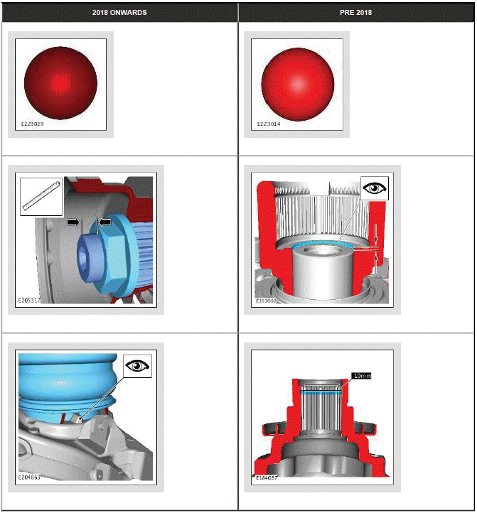
Fixings and Fasteners
This color is used on component that secures another by means of a thread, friction fit, or another form of lock/latching mechanism.
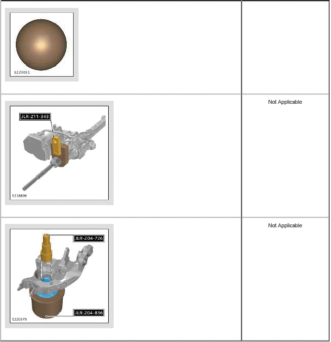
Special Tools - Active
This color is used for all special tools and general equipment when installed or removed as a single entity. This special tool color 'active' represents a tool been positioned or manipulated during the step.
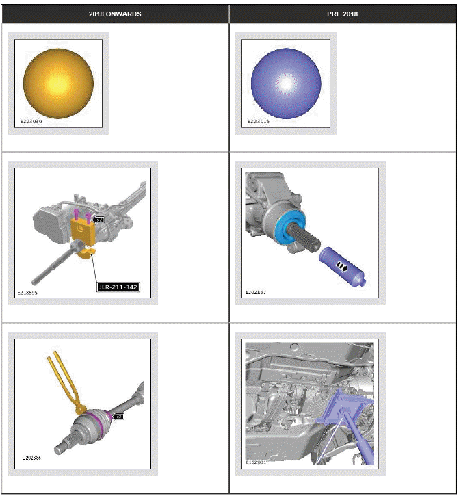
Special Tools - Passive
This color is used for all special tools and general equipment when already installed in previous step but they still remain part of the following steps.
Surrounding Components
This color is used for all non-focus surrounding components.
Surrounding Components - Alternative
This color is can be used for non-focus components to add further clarity and depth of field.
ILLUSTRATION SYMBOLS
Symbols are used inside the illustrations to enhance the information display.
Movement Symbols
Movement symbols provide detailed information to a required component movement. These component movements can be rotational or 1-3 dimensional movements.
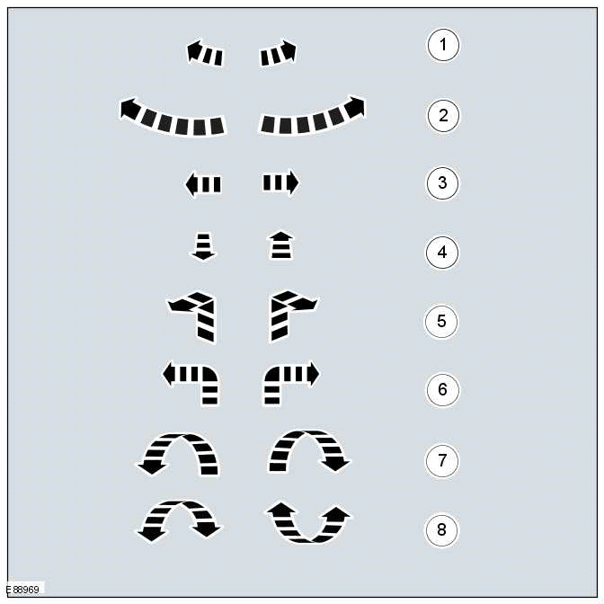
- Minor component movement clockwise/counterclockwise
- Major component movement clockwise/counterclockwise
- Component movement to the left/right/up/down
- Component movement towards/away
- 3 dimensional component movement
- 2 dimensional component movement
- 3 dimensional component rotation
- 3 dimensional component cycling
Turn Symbols
Turn symbols are used to provide further information on the direction or angle of component turns.
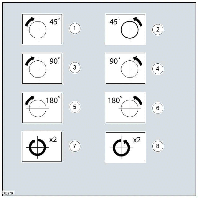
- Turn the component clockwise through 45º
- Turn the component counterclockwise through 45º
- Turn the component clockwise through 90º
- Turn the component counterclockwise through 90º
- Turn the component clockwise through 180º
- Turn the component counterclockwise through 180º
- Turn the component clockwise through 2 complete turns
- Turn the component counterclockwise through 2 complete turns
Pliers symbols
The pliers symbols are used to show which pliers is recommended to carry out a procedure step.
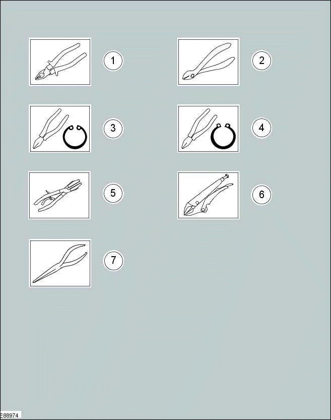
- Combination pliers
- Side cutter pliers
- Securing ring pliers - inner
- Securing ring pliers - outer
- Hose clamp pliers
- Locking pliers
- Long nose pliers
Drill symbols
The drill symbols are used to show which type and size of drill bit is recommended to carry out a procedure step.
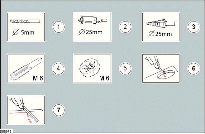
- Drill bit with a specified diameter
- Hole saw with a specified diameter
- Stepped drill bit with a specified diameter
- Tap with a specified diameter
- Die with a specified diameter
- Scraper for circular holes
- Scraper for straight edges
Cutting tool symbols
The cutting tool symbols are used to show which type of cutting tool is recommended to carry out a procedure step.
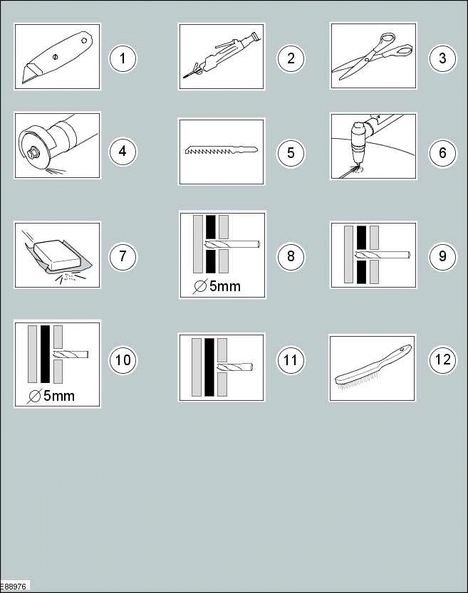
- Cutting knife
- Air body saw
- Scissors
- Grinder
- Jig saw
- Plasma cutter
- Sanding Paper
- Drill through the shown number of body panel layers with a specified diameter
- Drill through the shown number of body panel layers with a suitable diameter
- Drill through 1 body panel layer with a specified diameter
- Drill through 1 body panel layer with a suitable diameter
- Wire brush
Apply Chemical or load symbols
The apply chemical or load symbols are used to show where to apply which type of chemical or load to carry out a procedure step.
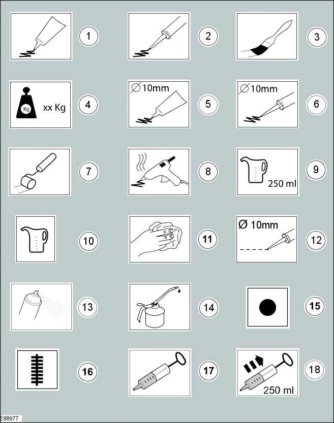
- Apply a bead from the specified tube
- Apply a bead from the specified cartridge
- Apply the specified chemical with a brush
- Apply the specified load to the specified component
- Apply a bead with a specific diameter from the specified tube
- Apply a bead with a specific diameter from the specified cartridge
- Apply the specified chemical with a roller
- Apply hot glue to the specified component
- Apply the specified amount of fluid from the fluid can
- Apply fluid from the fluid can
- Clean the specified component with the specified material
- Apply a broken bead from the specified tube
- Apply the specified chemical from a spray can
- Apply the specified lubricant to the specified component
- Apply spot welds to the specified component
- Apply a continuous weld to the specified component
- Handle the fluid using a syringe
- Extract the specified amount of fluid using a syringe
Measurement symbols
The measurement symbols are used to show where to measure which type of measurement to carry out a procedure step.
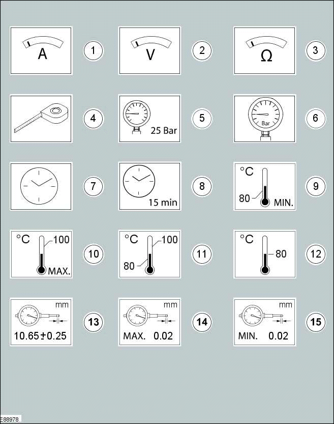
- Measure the current using a digital multimeter
- Measure the voltage using a digital multimeter
- Measure the resistance using a digital multimeter
- Measure the length/distance
- Check that the specified pressure is available using a suitable pressure gauge
- Measure the pressure at the specified port using a suitable pressure gauge
- Measure the time using a suitable stopwatch
- Wait for the specified period of time
- The specified task requires the specified minimum temperature
- The specified task requires the specified maximum temperature not to be exceeded
- The specified task requires the specified temperature range
- The specified task requires the specified temperature
- Measure and check for the specified value using a dial indicator gauge
- Measure and check for the specified MAX value using a dial indicator gauge
- Measure and check for the specified MIN value using a dial indicator gauge
General equipment symbols
The general equipment symbols are used to show where to use which type of general equipment to carry out a procedure step.
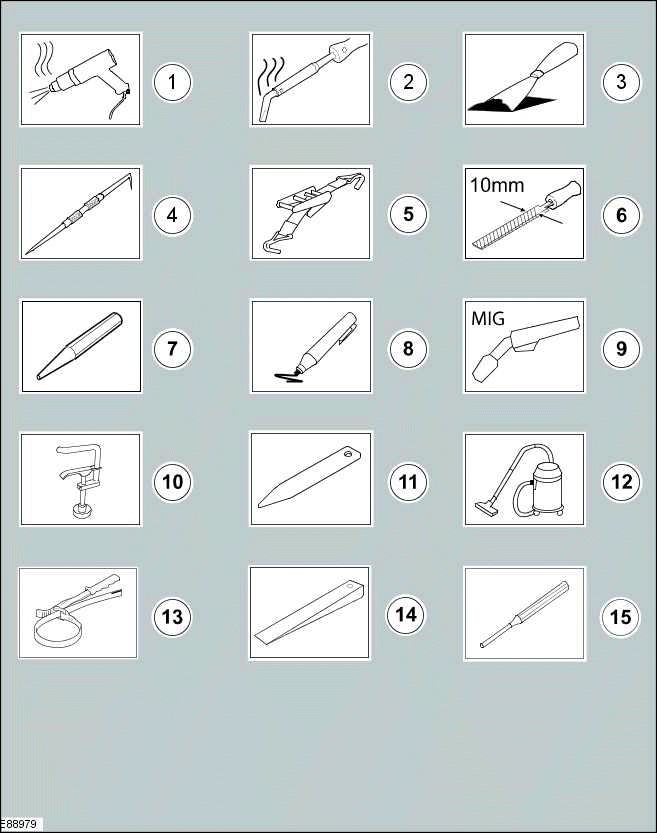
- Hot air gun
- Soldering iron
- Scraper
- Scriber
- Securing strap
- File with a specified size
- Center punch
- Marker
- Metal inert gas (MIG) welding equipment
- Hose clamp
- Interior trim remover
- Vacuum cleaner
- Strap wrench
- Wedge
- Pin Punch
Material symbols
The material symbols are used to show where to use which type of material to carry out a procedure step.
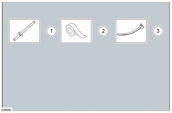
- Remove/Install the specified blind rivet
- Apply tape to the specified component/area
- Remove/Install the specified cable tie
Miscellaneous symbols
These symbols provide further information that is required to carry out a procedure step.
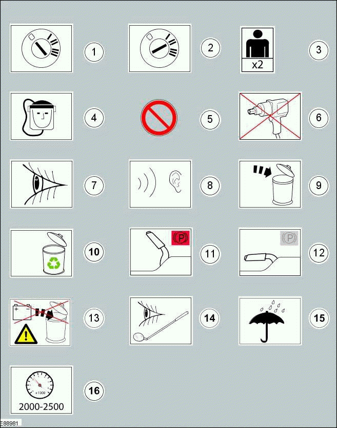
- Set the ignition switch to the 0 position
- Set the ignition switch to the II position
- The procedure step requires the aid of the specified number of supporting technicians
- Self contained breathing apparatus
- General prohibition used in combination with another symbol
- Do not use power tools
- Visual check
- Noise check
- Dispose the specified component
- Replaced by item 9 (Dispose the specified component)
- Set the engine speed to the specified value
- Fully apply the parking brake lever
- Fully release the parking brake lever
- Do not dispose of batteries into the waste bin
- Visual check using a mirror
- Area/component must be dry
Mandatory Protective Equipment
The protective equipment symbols advise to use mandatory protective equipment to avoid, or at least, reduce possible health and safety risks.
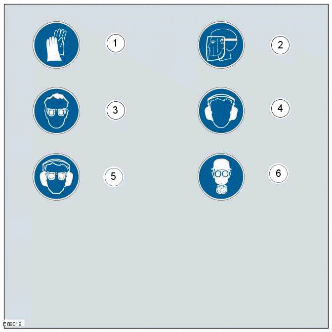
- Wear protective gloves
- Wear face guard
- Wear safety goggles
- Wear ear protectors
- Wear safety goggles and ear protectors
- Wear a respirator
Prohibition
The prohibition symbols are used to prohibit the specified actions to avoid or at least reduce possible component damage and health and safety risks.
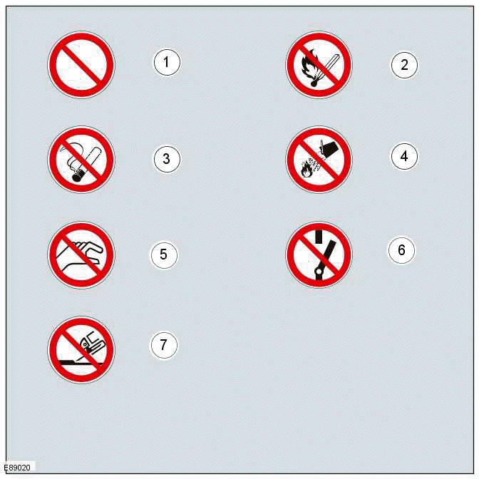
- General prohibition symbol
- No naked flames
- No smoking
- No water
- Do not touch
- Do not switch
- No grinding
Warning
The warning symbols are used to advise on hazardous conditions to avoid or at least reduce possible component damage and health and safety risks.
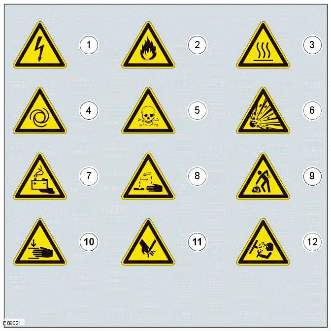
- Hazardous voltage/Electrical shock/Electrocution
- Fire Hazard/Highly flammable
- Burn hazard/Hot surface
- Automatic start-up
- Toxic
- Explosive material
- Battery hazard
- Corrosive material
- Lifting hazard
- Hand crush/Force from above
- Cutting of fingers or hand
- Pressure hazard
High Voltage (HV) and HV Mandatory Protective Equipment
The High Voltage (HV) symbols and HV protective equipment symbols advise to use mandatory HV protective equipment to avoid, or at least reduce, possible health and safety risks.
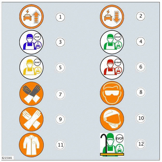
- Power up the High Voltage (HV) system
- Power down the High Voltage (HV) system
- Electric Vehicle Informed Person (EVIP)
- Electric Vehicle Competent Person (EVCP)
- Electric Vehicle Authorised Person (EVAP)
- Electric Vehicle Senior Authorised Person (EVSAP)
- Class 0 Over Gloves
- Class 0 Safety Glasses
- Class 0 1000 volt, insulated rubber gloves
- Class 1 High Voltage Safety mask
- Class 1 CAL12.4 fire retardant lab coat
- Safety assisting person with hook
READ NEXT:
 How To Use Diagnosis and Testing Procedures
Inspection and Verification
Visual Inspection Charts, Symptom Charts and other information charts (such
as diagnostic routines) or supplement
test procedures with technical specifications will naviga
Diesel Fuel System Health and Safety Precautions
DESCRIPTION AND OPERATION
WARNINGS:
Fuel may not give adequate warning before toxic or harmful effects
arise.
Exposure to fuel can be harmful and can cause severe health damage or
death.
Provi
Fluid Leaks
DESCRIPTION AND OPERATION
GENERAL PROCEDURE - FLUID LEAK DETECTION
SERVICE INSTRUCTION
NOTES:
Slight surface oil dampness without drops are acceptable and should
not be repaired as a leak
Be awa
SEE MORE:
Charging System
DIAGNOSIS AND TESTING
PRINCIPLE OF OPERATION
For a detailed description of the charging system and operation, refer to the
relevant description and operation section
of the workshop manual.
Battery Care Requirements (Description and Operation),
Quiescent Drain (Description and Operation).
PRINCIPLE
Front Row Seat - Vehicles With: Power Seats
REMOVAL AND INSTALLATION
REMOVAL
WARNINGS:
To avoid accidental deployment, the Restraints Control Module (RCM)
backup power supply must be
depleted. Wait at least 1 minute after disconnecting the startup battery
ground cable(s) before doing any
repair or adjustment to the Supplementary Restr
