
Land Rover Defender: Fluid Leaks
DESCRIPTION AND OPERATION
GENERAL PROCEDURE - FLUID LEAK DETECTION
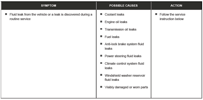
SERVICE INSTRUCTION
NOTES:
- Slight surface oil dampness without drops are acceptable and should not be repaired as a leak
- Be aware that fluid leaks from above any component may cause oil to collect on the engine and transmission undershield i.e. engine leaks, oil cooler pipe leaks, fuel leaks, coolant leaks
- Fixing the incorrect leak does not satisfy the customer
1. Remove any undershield or engine covers to gain access to the suspected leak area
2. Using a suitable degreaser, thoroughly degrease the suspected component all the way around as well as, approximately, 25-50mm (1-2 inches) above the suspected leak
3. Using a suitable leak detector spray, thoroughly coat the suspected component as well as, approximately, 25- 50mm (1-2 inches) above the suspected leak
4. Install the transmission/engine undershield and engine covers if removed
5. Complete a suitable road test and make sure that the engine gets to normal operating temperature
6. Remove any undershield or engine covers to gain access to the suspected leak area
7. Inspect the suspected component for fluid leaks, the detector spray should leave a trace from the leak area
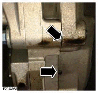
Engine oil leak example graphic. Oil is present between the engine and transmission mating faces, including evidence of oil in the 3 breather holes
8. Report or repair the source of the fluid leak
9. If no leak is found, continue diagnosis until the exact source of the leak is found
10. Install the transmission/engine undershield and engine covers if removed
READ NEXT:
 Health and Safety Precautions
DESCRIPTION AND OPERATION
INTRODUCTION
Modern vehicles contain many materials and liquids which if not handled with
care can be hazardous to both personal
health and the environment. Also, many of th
Acids and Alkalis
For example - alkalis such as caustic soda used in cleaning materials; acids
such as sulphuric acid used in batteries.
Both alkalis and acids are irritant and corrosive to the skin, eyes, nose and
t
Adhesives and Sealants
Many adhesives and sealants are highly flammable - OBSERVE NO SMOKING POLICY.
These items, should be
stored in flameproof cabinets in No Smoking areas. Cleanliness and tidiness in
use should be obse
SEE MORE:
C-Pillar Side Impact Sensor
REMOVAL AND INSTALLATION
REMOVAL
WARNINGS:
To prevent accidental deployment, you must power down the Restraints
Control Module (RCM). Wait at
least 1 minute after you disconnect the startup battery ground cable before
you do any work on the
Supplementary Restraint System (SRS). If you do not
Wheel Arch Protection
WHEEL ARCH PROTECTION - PART NUMBER: 90:
VPLEP0381, VPLEP0382, 110: VPLEP0379,
VPLEP0380
REMOVAL AND INSTALLATION
WARNING:
Accessories which are not correctly installed can be dangerous. Read the
instructions carefully prior to
installation. Comply with instructions at all times. If in doubt, conta
