
Land Rover Defender: Description
SHOCK ABSORBERS
The adaptive shock absorbers are nitrogen gas and oil filled monotube units. The shock absorbers are continuously variable, which allows the damping force to be electrically adjusted when the vehicle is being driven. The shock absorbers provide the optimum compromise between vehicle control and ride comfort.
The shock absorbers have an electrical connector on the end of the piston rod, in the center of the top mount.
In each shock absorber, the damping adjustment is achieved by a variable orifice operated by a solenoid. The orifice is used to open up alternative paths to allow oil-flow within the shock absorber. When de-energized the bypass is closed and all the oil flows through the main (firm) piston. When energized the solenoid moves an armature and control blade, which work against a spring. The control blade incorporates an orifice which slides inside a sintered housing to open up the bypass as required. When the shock absorber is compressed the oil flows from the lower portion of the shock absorber then through a hollow piston rod, which is a separate soft (comfort) valve. The oil then flows through the slider housing and orifice and into the upper portion of the shock absorber, thereby bypassing the main (firm) valve. In rebound the oil flows in the opposite direction.
In the firm setting oil flows through the main (firm) valve only, although when the bypass is opened by variable amounts, the oil flows through both valves to provide a pressure balance. When fully energized the solenoid moves the armature and therefore the slider to the maximum extension and opens the orifice completely. The shock absorber operates continuously between these 2 boundary conditions.
The solenoid in each shock absorber is operated by a 526 Hz Pulse Width Modulated (PWM) signal from the CHCM.
The CHCM controls the PWM duty ratio to provide 1.5A to operate the shock absorber in the soft setting. When deenergized (0.0A) the shock absorber is in the firm setting. The current varies continuously as required to increase and decrease the damping individually in each of the shock absorbers.
Sectioned Views of Shock Absorber Operating States
.png)
- Firm setting
- Soft setting
- Main oil flow
- Bypass oil flow
- Bypass valve (open)
- Main valve
- Tube
- Bypass valve (closed)
- Piston and rod assembly
ACCELEROMETERS
NOTE: Model 110 vehicle is shown, model 90 vehicle is similar.
.png)
- Front accelerometers (quantity 2)
- Rear accelerometer
There are 3 accelerometers used in the Adaptive Damping (AD) system, 2 at the front of the vehicle and 1 at the rear.
The accelerometers measure acceleration in the vertical plane and output a corresponding analog signal to the CHCM. The algorithms in the CHCM calculate the heave, pitch and roll motions of the vehicle, which are used to control body motion.
Each accelerometer is connected to the CHCM through 3 wires, which supply ground, 5V supply and signal return.
The sensing element comprises a single parallel plate capacitor, 1 plate of which moves relative to the other dependant on the force (acceleration) applied. This causes the capacitance to change as a function of applied acceleration. This capacitance is compared with a fixed reference capacitor in a bridge circuit and the signal is processed by means of a dedicated integrated circuit to generate an output voltage that varies as a function of applied acceleration. The sensors output a signal voltage of approximately 1 V/g +- 0.05 V/g. When the vehicle is stationary, each accelerometer outputs approximately 2 volts.
HEIGHT SENSORS
Front Height Sensor
.png)
- Lever arm
- Bracket
- Sensor body
- Electrical connector
Rear Height Sensor
.png)
- Sensor body
- Lever arm
- Electrical connector
There are 4 height sensors that are used in the air suspension system, 2 for the front suspension and 2 for the rear suspension. On each suspension height sensor, the sensor arm and sensor link convert linear movement of the suspension into rotary movement of the sensor shaft.
The suspension height sensors measure suspension displacement at each corner of the vehicle and output a corresponding analog signal to the CHCM. The algorithms in the CHCM calculate the position, velocity and frequency content of the signals. The output is used in the control of vehicle systems, for example air suspension, active damping or headlamp leveling.
Height Sensor Voltage
.png)
- Sensor voltage
- Angle of rotation
- Outside measuring range
- Voltage output
- +- 40º measuring range
CHASSIS CONTROL MODULE
NOTE: Model 110 vehicle is shown, model 90 vehicle is similar.
.png)
The CHCM is the main controller of the air suspension system. The CHCM monitors the height of each corner of the vehicle through 4 height sensors, which are mounted in-board of each road wheel. The CHCM is fixed to a bracket in the luggage compartment, behind the right side trim panel.
When a new CHCM is installed, the air suspension software must be loaded and the system calibrated using a JLR approved diagnostic equipment. The air suspension system does not operate until the calibration is completed.
AIR SUSPENSION SWITCHPACK - INTERACTIVE CONTROL INTERFACE MODULE 'A'
.png)
- Off-road height indicator
- Raise suspension height
- Normal height indicator
- Lower suspension height
- Access height indicator
- Suspension locked in access height - indicator
The air suspension control switch is a part of the ICIMA and located in the instrument panel.
The switch is a 3 position, non-latching switch which allows selection of the following driver selectable states:
- Off-road mode
- Normal height
- Access height
- Locked at access height
The switch has 6 symbols which illuminate to show the current selected height state and the direction of movement.
The raise and lower symbols flash and a warning tone is to be emitted from the instrument cluster sounder when a requested height change is not allowed. For example, when the vehicle speed is too fast or the air suspension system is in a waiting state.
The air suspension system is in a waiting state or the system overrides the driver selection because the speed is approaching an automatic height change threshold.
The driver can also ignore the system warnings signals and allow the height to change automatically. For example, accelerate to more than 40 km/h (25 mph) when locked to access height. This makes the control module automatically change the ride height to on-road mode.
AIR SUSPENSION SWITCHPACK - LUGGAGE COMPARTMENT
NOTE: Model 110 vehicle is shown, model 90 vehicle is similar.
.png)
The rear switchpack is located in the left luggage compartment trim panel. The rear switchpack sends signals to the CHCM on hardwired connections.
Rear height adjust is useful when loading or unloading the vehicle, connecting or disconnecting a trailer, and when maneuvering a connected trailer.
The operation method of the rear switchpack is in the operation section below.
FRONT AND REAR VALVE BLOCKS
Front Valve Block
.png)
- Electrical connector
- Rubber bushes
- Air pipe connection of the front right air spring
- Air pipe connection of the rear valve block
- Air pipe connection of the front left air spring
The front valve block controls the air supply and distribution to the front air springs. The front valve block contains 3 solenoid operated valves; 2 corner valves and 1 cross-link valve. The front valve block is located on the right side behind the secondary bulkhead panel and fixed with 3 rubber bushes to a bracket. The front valve block is controlled by the CHCM on hardwired connections.
Rear Valve Block
.png)
- Electrical connector
- Air pipe connection of the suspension air supply unit
- Air pipe connection of the front valve block
- Air pipe connection of the rear left air spring
- Air pipe connection of the reservoir
- Rubber bushes
- Air pipe connection of the rear right air spring
The rear valve block is located behind the rear right wheel arch liner and fixed with 3 rubber bushes to a bracket.
The rear valve block controls the:
- Air supply and distribution to the rear air springs, and
- Controls air distribution to and from the air reservoir.
The rear valve block contains:
- The 2 corner valves
- 1 cross-link valve
- 1 reservoir valve
- And the system's pressure sensor.
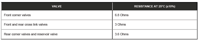
Each of the valve solenoids is individually controlled by the CHCM.
The solenoids have the following resistance values:
SUSPENSION AIR SUPPLY UNIT
NOTE: Model 110 vehicle is shown, model 90 vehicle is similar.
.png)
- Inner air supply housing cover
- Exhaust silencer
- Air drier
- Intake air filter
- Compressor
- Electric motor
- Electrical connectors
- Air outlet
The suspension air supply unit comprises the following major components:
- A 2-stage piston compressor
- A 12V electric motor
- A solenoid operated exhaust pilot valve
- A pneumatically operated exhaust valve
- An air dryer unit
- A compressor temperature sensor.
The air supply housing surrounds the suspension air supply unit. The air supply housing is double layer box which is lined with insulating foam which suppresses the operating noise of the suspension air supply unit. Each layer of the box has a plastic moulded base and a pressed steel lid.
The suspension air supply unit supplies dry compressed-air into the air suspension system where it is directed into the air springs or the reservoir by solenoid operated valves.
Air can be exhausted from the system when required
- By the opening of an air spring.
- By the opening of the reservoir valve in addition to the exhaust valve, which is part of the suspension air supply unit.
The compressor operates to pressurize either the reservoir or to inflate 1 or more of the air springs.
The compressor does not operate without the engine running, with the following exceptions:
- During remote operation or during rear height adjust operation to raise the vehicle to allow for the attachment of a trailer.
- When under control of the JLR approved diagnostic equipment.
There are a number of conditions that inhibit the operation of the suspension air supply unit. It is vitally important that these system inhibits are not confused with a system malfunction. A full list of suspension air supply unit inhibits are given in the air compressor section of this document.
Electric Motor
The electric motor is a 12V Direct Current (DC) motor with a nominal operating voltage of 13.5V. The motor drives a crank which has an eccentric pin to which the 2 -stage piston assembly is attached.
Air Compressor
The compressor comprises a motor driven 2-stage piston assembly which operates in cylinders at opposite ends of the compressor body. The motor rotates a crank which moves the pistons up and down in their cylinder bores. The low-pressure cylinder delivers intermediate compressed air to the high-pressure cylinder on the down stroke. The highpressure piston delivers fully compressed air with the up stroke which is passed, through the delivery valve, through the air dryer and into the air suspension system.
A temperature sensor is installed in the cylinder head. The sensor is connected to the CHCM which monitors the cylinder temperature and can suspend compressor operation if an overheat condition occurs.
The following table shows the control module operating parameters for the differing suspension air supply unit functions and the permitted compressor cylinder head operating temperatures.
.png)
Air Drier
Attached to the compressor is the air dryer which contains a desiccant for removing moisture from the compressed air.
Pressurized air is passed through the air dryer which removes any moisture in the compressed air before it is passed into the suspension system.
When the air springs are deflated, the exhaust air passes back through the air dryer, removing the moisture from the unit and regenerating the desiccant.
The air dryer is an essential component in the system making sure that only dry air is present in the system. If moist air is present, freezing can occur resulting in poor system operation or component malfunction or failure.
To make sure the air-dryer continues to perform correctly, it is essential during servicing, that
- The affected air springs are deflated using the correct deflation procedure
- Air is removed from the air reservoir using the correct procedure.
Pilot Exhaust Valve
The exhaust valve operates when the pilot exhaust valve is opened, allowing air to be exhausted quickly.
The pilot exhaust valve is connected to the air delivery gallery, downstream of the air drier. The pilot valve, when opened, operates the slave exhaust valve, allowing air to exhaust the system.
When the solenoid is energized, pilot air moves the slave exhaust valve plunger. The exhaust valve plunger allows the pressurized air from the air suspension system to pass through the air drier to the atmosphere.
SUSPENSION AIR SUPPLY UNIT SPECIFICATIONS
.png)
.png)
Resistance values vary with coil temperature. Resistance of test leads must be measured before any readings are taken. Resistance value of the test leads must be subtracted from final solenoid resistance value.
AIR RESERVOIR
The reservoir is an air storage vessel which provides faster air suspension lift times by the immediate availability of pressurized air into the system. The nominal working pressure of the reservoir is 17.5 bar gauge. The reservoir has a capacity of 11 liters.
For the model 110 vehicles there is 1 reservoir with a volume of 11 Liters.
.png)
For the model 90 vehicles the 11 Liter volume is achieved by linking 2 reservoirs.
.png)
On Model 110 vehicles the rearward end of the reservoir has an air fitting which provides for the connection of the air hose between the reservoir and the rear valve block. On Model 90 vehicles the rearward end of both reservoirs has an air fitting which provides for the connection of the air hose connecting the reservoirs. The right reservoir has a second air fitting which provides for the connection of the air hose between the reservoir and the rear valve block.
The CHCM assumes the reservoir has sufficient pressure, which is measured before a vehicle raise is started. The CHCM then uses a software model to operate the compressor as required.
AIR SPRINGS
.png)
- Front air spring and shock absorber assembly
- Rear air springs (shock absorber shown for clarity)
The air springs work on the same principle but the front and rear components differ in construction:
- The front units are integral with shock absorber
- The rear units are separate from the shock absorber.
The air springs are manufactured from a flexible rubber. Each air spring forms an air tight cavity which provides the required spring rate for each corner of the vehicle.
As the air spring is compressed, the rubber material rolls onto the air spring's piston, compressing the air inside. An air connection port is located on the top of each spring and allows air to be added or removed from each spring. The port is connected through a air line connector connector and a plastic tube to the front or rear valve block.
Replacement of an individual air spring does not require a full depressurization of the air suspension system. Only the corner concerned needs to be depressurized. This is achieved using routines in the JLR approved diagnostic system.
When servicing of an air spring or a full system depressurization is required, the weight of the vehicle must be supported before the system is depressurized. On reassembly, the pipes between air springs and the valve blocks must be must be connected before the weight of the vehicle is applied to the air springs. Rear air springs must also be pressurized before the weight of the vehicle is applied to them.
READ NEXT:
 Operation
CHASSIS CONTROL MODULE
The CHCM uses a combination of information from other system modules and data
from the accelerometers and
suspension height sensors to measure the vehicle and suspension states
Control Diagram
Control Diagram 1 of 2 - Adaptive Damping
A = HARDWIRED:
AL = PWM:
AX = FLEXRAY:
BA = HS CAN HUMAN MACHINE INTERFACE (HMI) SYSTEMS BUS.
CHCM
RCM
Powertrain Control Module (PCM)
ABS
Terrain R
Vehicle Dynamic Suspension - Diagnosis and Testing
PRINCIPLES OF OPERATION
For additional information on the operation of the air suspension system,
refer to the relevant section of the workshop manual.
INSPECTION AND VERIFICATION
WARNING:
Before car
SEE MORE:
Second Row Center Seatbelt Buckle - [+] 7 Seat Configuration, 110
REMOVAL AND INSTALLATION
PART(S)
REMOVAL
NOTE:
This procedure contains some variation in the illustrations depending
on the vehicle specification, but the
essential information is always correct.
This procedure contains illustrations showing certain components
removed to provide extra clari
Door Window Motor Initialization
GENERAL PROCEDURES
NOTES:
Make sure that the vehicle battery is fully charged before carrying
out this procedure.
After the battery has been disconnected or a new window regulator and
motor or door module has been
installed, it is necessary to initialize each door window motor separately
t
