
Land Rover Defender: Chequered Body Protection Kit
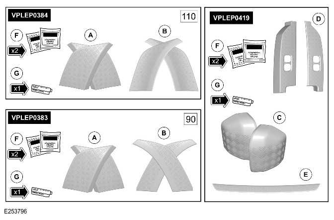
CHEQUERED BODY PROTECTION KIT - PART NUMBER: VPLEP0419, 90: VPLEP0383, 110: VPLEP0384
REMOVAL AND INSTALLATION
WARNING: Accessories which are not correctly installed can be dangerous. Read the instructions carefully prior to installation. Comply with instructions at all times. If in doubt, contact your nearest approved retailer.
CAUTIONS:
- If protective wax has been applied to the vehicle it must be thoroughly removed before starting this procedure.
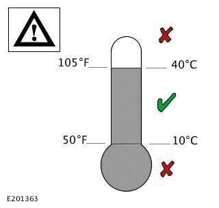
- The vehicle must be clean, dry and at workshop temperature. Vehicles moved into the workshop from cold or wet conditions should be dried and left to stand for a minimum of 2 hours.
NOTES:
- This procedure contains some variation in the illustrations depending on the vehicle specification, but the essential information is always correct.
- This procedure contains illustrations for left side components, right side components are similar.
- The chequered body protection kit can be installed to vehicles that are already equipped with wheel arch protection. Order only the common kit VPLEP0419, for vehicles with 90 or 110 wheelbase that are equipped with wheel arch protection.
- Order kits VPLEP0383 and VPLEP0419 if installing the chequered body protection to vehicles with 90 wheelbase that are not equipped with wheel arch protection.
- Order kits VPLEP0384 and VPLEP0419 if installing the chequered body protection to vehicles with 110 wheelbase that are not equipped with wheel arch protection.
- The rear scuff chequer plate (E) should not installed if the vehicle is equipped with the bright rear scuff plate (VPLEP0447).
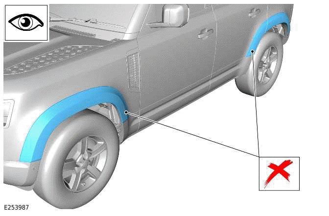
CAUTION: If the illustrated wheel arch protection kit is installed then kits VPLEP0383 or VPLEP0384 cannot be installed.
INSTALLATION
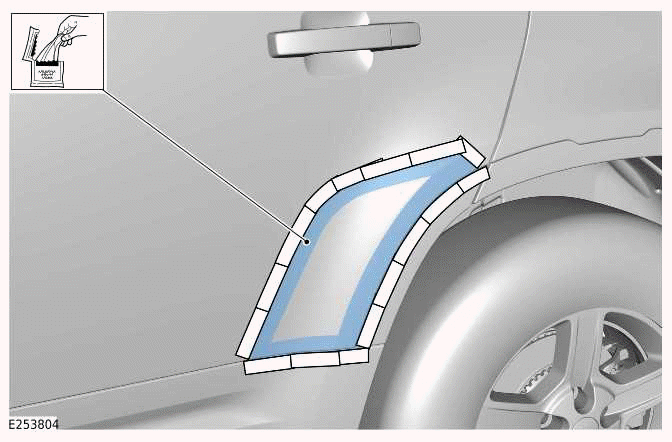
1.
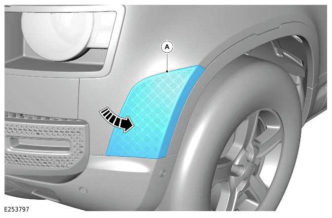
Place the front wheel arch chequer plate (A) on the body for masking purposes only.
2.
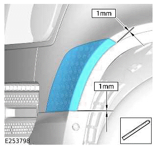
3.
When in position, secure with suitable tape and mask the edge of the chequer plate on the vehicle body.
Remove the chequer plate.
4.
WARNING: Make sure to wear suitable personal protective equipment when using cleaner or adhesion promoter in the following steps.
CAUTION: Allow to dry for a minimum of 2 minutes before proceeding to the next step.
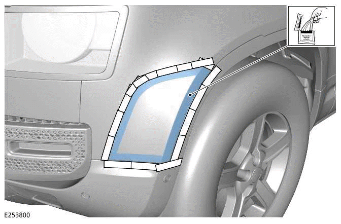
Using the cleaner (F) supplied in the kit, clean the illustrated area.
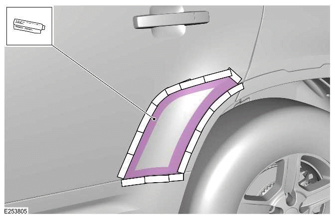
5.
CAUTION: Allow to dry for a minimum of 5 minutes before proceeding to the next step.
NOTE: To activate the adhesion promoter, hold the tube between your finger and thumb, squeeze the middle of the tube until you here a crack noise, shake the tube gently and the fluid will flow to the tip.
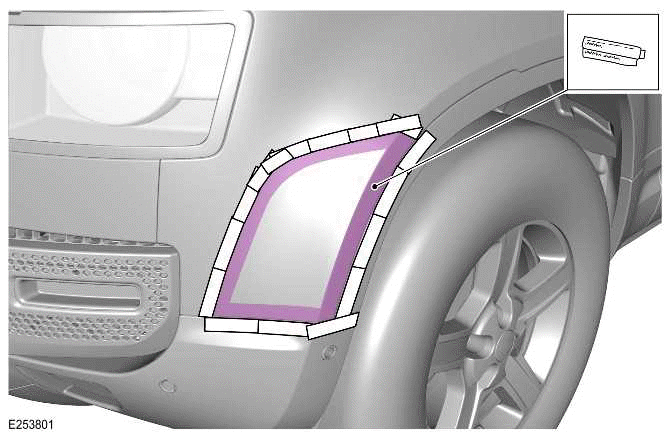
Using the adhesion promoter (G) supplied in the kit, wipe the illustrated area.
6. Remove the masking tape.
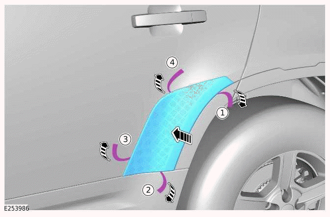
7.
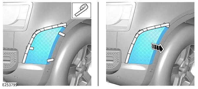
CAUTION: Control the specified gaps when peeling away the backing from the adhesion strips.
NOTE: Firmly push the edges of the front wheel arch chequer plate along the outside edges to assure good adhesion to the fender.
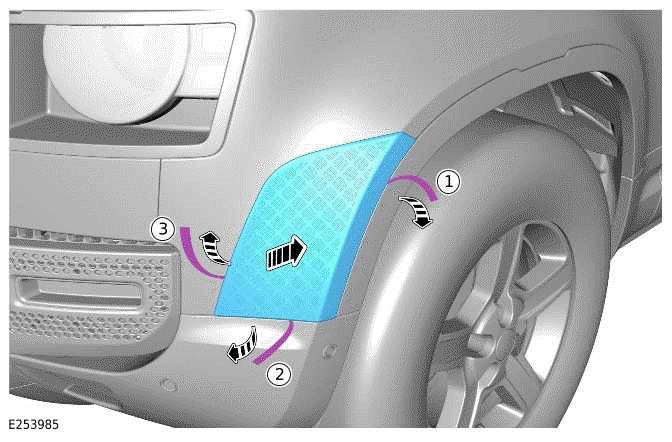
Install the front wheel arch chequer plate (A). While applying pressure to the chequer plate, peel away the backing from the adhesion strips in the order as illustrated.
8.
NOTE: Illustration shows 110 wheelbase. For vehicle with 90 wheelbase the rear wheel arch chequer plate is installed to the quarter panel instead of the rear door.
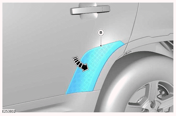
Place the rear wheel arch chequer plate (B) on the body for masking purposes only.
9.
NOTE: Illustration shows 110 wheelbase. For vehicle with 90 wheelbase the rear wheel arch chequer plate is installed to the quarter panel instead of the rear door.
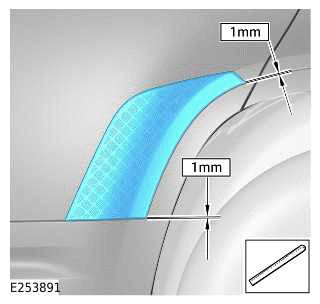
10.
NOTE: Illustration shows 110 wheelbase. For vehicle with 90 wheelbase the rear wheel arch chequer plate is installed to the quarter panel instead of the rear door.
When in position, secure with suitable tape and mask the edge of the chequer plate on the vehicle body.
Remove the chequer plate.
11.
WARNING: Make sure to wear suitable personal protective equipment when using cleaner or adhesion promoter in the following steps.
CAUTION: Allow to dry for a minimum of 2 minutes before proceeding to the next step.
NOTE: Illustration shows 110 wheelbase. For vehicle with 90 wheelbase the rear wheel arch chequer plate is installed to the quarter panel instead of the rear door.
Using the cleaner (F) supplied in the kit, clean the illustrated area.
12.
CAUTION: Allow to dry for a minimum of 5 minutes before proceeding to the next step.
NOTES:
- Illustration shows 110 wheelbase. For vehicle with 90 wheelbase the rear wheel arch chequer plate is installed to the quarter panel instead of the rear door.
- To activate the adhesion promoter, hold the tube between your finger and thumb, squeeze the middle of the tube until you here a crack noise, shake the tube gently and the fluid will flow to the tip.
Using the adhesion promoter (G) supplied in the kit, wipe the illustrated area.
13. Remove the masking tape.
14.
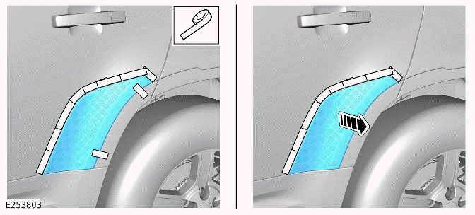
CAUTION: Control the specified gaps when peeling away the backing from the adhesion strips.
NOTES:
- Firmly push the edges of the rear wheel arch chequer plate along the outside edges to assure good adhesion to the body.
- Illustration shows 110 wheelbase. For vehicle with 90 wheelbase the rear wheel arch chequer plate is installed to the quarter panel instead of the rear door.
Install the rear wheel arch chequer plate (B). While applying pressure to the chequer plate, peel away the backing from the adhesion strips in the order as illustrated.
15.
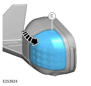
Place the mirror chequer plate (C) on the mirror for masking purposes only.
16.
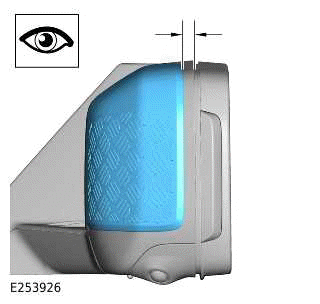
Make sure the mirror chequer plate is parallel to the mirror body.
17.
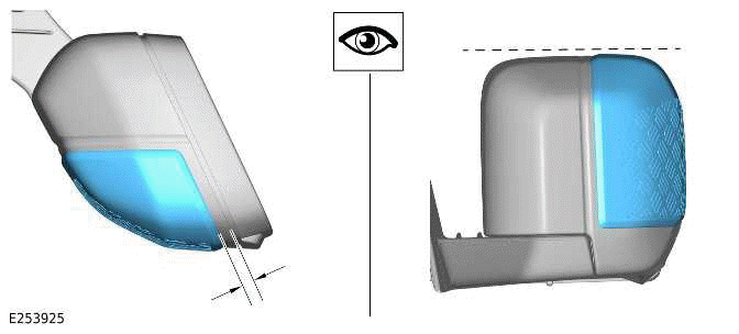
Make sure the mirror chequer plate is parallel to the mirror body.
18.
When in position, secure with suitable tape and mask the edge of the chequer plate on the mirror body.
Remove the chequer plate.
19.
WARNING: Make sure to wear suitable personal protective equipment when using cleaner or adhesion promoter in the following steps.
CAUTION: Allow to dry for a minimum of 2 minutes before proceeding to the next step.
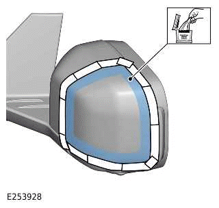
Using the cleaner (F) supplied in the kit, clean the illustrated area.
20.
CAUTION: Allow to dry for a minimum of 5 minutes before proceeding to the next step.
NOTE: To activate the adhesion promoter, hold the tube between your finger and thumb, squeeze the middle of the tube until you here a crack noise, shake the tube gently and the fluid will flow to the tip.
.png)
Using the adhesion promoter (G) supplied in the kit, wipe the illustrated area.
21. Remove the masking tape.
22.
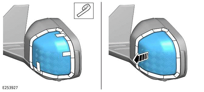
CAUTION: Control the specified gaps when peeling away the backing from the adhesion strips.
NOTE: Firmly push the edges of the chequer plate along the outside edges to assure good adhesion to the mirror.
.png)
Install the mirror chequer plate (C). While applying pressure to the chequer plate, peel away the backing from the adhesion strips in the order as illustrated.
23.
CAUTIONS:
- Make sure there are no remaining clips left in the vehicle body.
- Protect the surrounding paintwork and trim to avoid damage.
.png)
Remove the tail lamp outer finisher.
24.
.png)
Install the tail lamp outer finisher chequer plate.
25.
.png)
Measure and mark the center of the rear bumper.
26.
.png)
Measure and mark the center of the rear scuff chequer plate (E).
27.
.png)
Line up both the center marks and place the rear scuff chequer plate (E) on the bumper for masking purposes only.
28.
.png)
When in position secure the chequer plate on the bumper with suitable tape.
29.
.png)
Mask the edge of the chequer plate on the bumper. Remove the chequer plate.
30.
WARNING: Make sure to wear suitable personal protective equipment when using cleaner or adhesion promoter in the following steps.
CAUTION: Allow to dry for a minimum of 2 minutes before proceeding to next step.
.png)
Using the cleaner (F) supplied in the kit, clean the illustrated area.
31.
CAUTION: Allow to dry for a minimum of 5 minutes before proceeding to next step.
NOTE: To activate the adhesion promoter, hold the tube between your finger and thumb, squeeze the middle of the tube until you here a crack noise, shake the tube gently and the fluid will flow to the tip.
.png)
Using the adhesion promoter (G) supplied in the kit, wipe the illustrated area.
32. Remove the masking tape.
33.
CAUTION: Control the aligned position when peeling away the backing from the adhesion strips.
NOTE: Firmly push the edges of the chequer plate, along the full length, to make sure there is good adhesion to the bumper.
.png)
Install the rear scuff chequer plate (E). While applying pressure to the chequer plate, peel away the backing from the adhesion strips in the order as illustrated.
READ NEXT:
 Matte Bonnet Decal
MATTE BONNET DECAL - PART NUMBER:
VPLEB0438
REMOVAL AND INSTALLATION
WARNING:
Accessories which are not correctly installed can be dangerous. Read the
instructions carefully prior to
installation. Co
Front Mudflaps
FRONT MUDFLAPS - PART NUMBER: VPLEP0387,
VPLEP0389
REMOVAL AND INSTALLATION
WARNING:
Accessories which are not correctly installed can be dangerous. Read the
instructions carefully prior to
installat
Rear Mudflaps
REAR MUDFLAPS - PART NUMBER: VPLEP0388,
VPLEP0390
REMOVAL AND INSTALLATION
WARNING:
Accessories which are not correctly installed can be dangerous. Read the
instructions carefully prior to
installati
SEE MORE:
Rain sensor
Note: Static droplets may not be detected
when the vehicle is first started. A single
wipe should be used to clear the
windshield.
Note: If the wash/wipe control is in the
AUTO position, the wipers do not operate
if either of the front doors are open.
Note: In dry and often sunny conditions,
optical
Second Row Seatbelt Retractor - 90
REMOVAL AND INSTALLATION
PART(S)
REMOVAL
WARNING:
To prevent accidental deployment, you must power down the Restraints
Control Module (RCM). Wait at
least 1 minutes after you disconnect the startup battery ground cable before
you do any work on the
Supplementary Restraint System (SRS). If y
