
Land Rover Defender: Pipes and Hoses
When removing or installing flexible hydraulic pipes and hoses, make sure that the following procedures are observed to make sure component serviceability:
- Prior to removal, clean area around hose or pipe end which is to be disconnected.
- Obtain appropriate blanking plugs or caps before disconnecting hose or pipe end fittings in order that connections can be plugged immediately following disconnection.
- Always install blanking plugs or caps to pipes and unions immediately following disconnection.
- Clean hose or pipe and blow through with an air line.
WARNING: Suitable eye protection must be worn.
- Check hoses externally for cracks, separation of plies, security of end fittings and external damage; replace faulty hoses.
- Check pipes for signs of corrosion and chafing, replace as necessary.
CAUTION: If pipes are found to be chafed, rectify clips, mounting points etc., to prevent further problems in service.
- When installing hoses, make sure that no unnecessary bends are introduced and that hoses are not kinked, twisted or positioned close to potential chafing points.
- When installing pipes, make sure that pipes are positioned and clipped clear of potential chafing points.
- Always replace sealing washers installed to banjo bolts, sealing plugs etc, unless stated otherwise in the procedure.
- Always use a backing spanner when tightening unions and do not over tighten union nuts or banjo bolts.
- After engagement of 'quick-fit' connection hoses, perform a 'tug' test to make sure connection is secure.
- After any work on hydraulic systems, always check for fluid leaks whilst a second operator applies working pressure to the brake pedal or operates the system that has been worked on.
Fuel system hoses
Some fuel hoses are made up of two laminations, an armoured rubber outer sleeve and an inner viton core. Whenever a hose is removed, make sure that the inner bore is inspected to check that the viton lining has not become separated from the outer sleeve.
WARNING: Never attempt to repair fuel hoses or rectify leaking 'quick-fit' connectors. The fuel hose and connectors must be replaced as an assembly.
Fuel system hose clips
Certain fuel system hose clips are of the 'break-off head' type where a slot in the screw head shears off when the clip is tightened to a specific torque. These clips may be removed using a screwdriver and must be replaced with new clips on reassembly. Clips must be tightened until the portion of the slot shears off. Do not attempt to tighten clips by any other method, do not install any other type of clip.
'Quick-fit' connections are also installed to certain fuel hoses. After engagement of 'quick-fit' connections, perform a 'tug' test to make sure connection is secure.
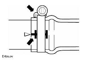
Other fuel system hose clips are of the 'Jubilee' type and there may be a tamper proof cover installed over the screw head. This cover must be carefully removed before slackening the clip and should be replaced after final tightening, ensuring that the internal hexagon on the cover is correctly located on the clip screw.
Cooling system hoses
CAUTION: The following precautions must be observed to make sure that the integrity of the cooling system hoses and their connection to the system is maintained.
Hose orientation and connection
Correct orientation of cooling system hoses is important to make sure that hoses do not become fatigued or damaged through contact with adjacent components.

Where orientation marks are provided on the hose and corresponding component, the marks must be aligned when the hose is installed. Hoses must be installed fully on to their connection points, usually a moulded form on a pipe provides a positive indicator.
Hose clips
Markings are usually provided on the hose to indicate the correct clip position. If no markings are provided, position the clip directly behind the retaining lip at the end of the stub pipe. Worm drive clips should be orientated with the crimped side of the drive housing facing towards the end of the hose or the hose may become pinched between the clip and the stub pipe retaining lip. Unless otherwise stated, worm drive clips should be tightened to 3 Nm (2 lb-ft).
Make sure that hose clips do not foul adjacent components.
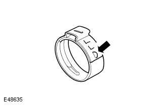
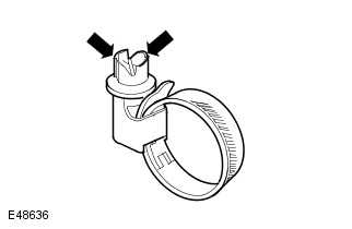
Oetiker clips may be removed by bending the tag (arrowed) and releasing the free end of the clip. Clips must not be reused.
When installing new clips, make sure clip is positioned on hose before tightening and make sure that when clip is tightened, the tag is located in the longitudinal slot in the free end of the clip (arrowed in illustration).
'Quick-fit' connections are also installed to certain hoses/pipes. Inspect 'quick-fit' connections for damage, prior to connection. Replace if damaged. After engagement of 'quick-fit' connections, perform a 'tug' test to make sure connection is secure.
Heat protection
Always make sure that heat shields and protective sheathing are in good condition; replace if damage is evident.
Particular care must be taken when routing hoses close to hot engine components such as the exhaust manifolds and exhaust gas recirculation (EGR) pipes. Hoses will relax and deflect slightly when hot, make sure this movement is taken into account when routing and securing hoses.
READ NEXT:
 Electrical Precautions
GENERAL
The following guidelines are intended to make sure the safety of the operator
whilst preventing damage to the
electrical and electronic components of this vehicle.
EQUIPMENT
Prior to commenci
Supplemental Restraint System (SRS) Precautions
WARNING:
Do not install rear facing child seats in the front passenger seat.
The SRS contains components which are potentially hazardous to service
personnel if not handled correctly. The
following g
Air Bag and Pre-Tensioner Deployment
WARNING:
During deployment parts of the air bag module become hot enough to burn you.
Wait 30 minutes after
deployment before touching the air bag module.
Deployment procedures and precautions as det
SEE MORE:
Child Seat - Infant Carrier (0kg-13kg)
CHILD SEAT - INFANT CARRIER (0KG-13KG) - PART
NUMBER: VPLRS0397
REMOVAL AND INSTALLATION
WARNING:
Accessories which are not correctly installed can be dangerous. Read the
instructions carefully prior to
installation. Comply with instructions at all times. If in doubt, contact your
nearest approved
Cleaning screens and displays
Do not polish the Instrument panel.
Polished surfaces are reflective, and may
interfere with the driver's view. Driving
with an obstructed view may result in
accidents causing serious injury or
death.
When cleaning around electrical
equipment, such as switches, make sure
fluids do not leak into a
