
Land Rover Defender: Folding the center seatback

Make sure that you have read and fully understood the relevant warnings before using any of the features in this section.
Note: The second row center seat belt incorporates a locking feature. The locking feature prevents the seat belt from being pulled out too far when the seatback is folded flat. To reset the feature, when returning the seatback to the upright position, extract the seat belt webbing until it stops. Return the seat belt webbing a small amount. The seat belt then operates as normal.
Note: Head restraints need to be removed to achieve the maximum cargo space.
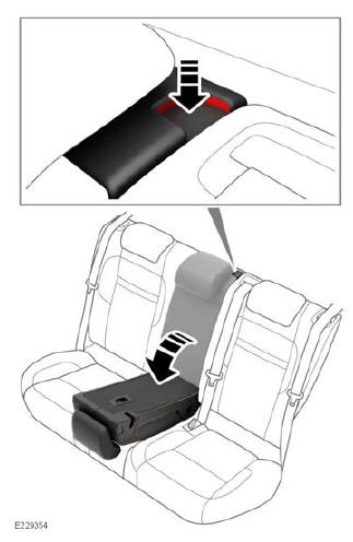
The center rear seatback can be released separately. To release the center rear seatback, press and hold the release button. Simultaneously fold the seatback forward.
To fold the center seatback: Press the release button on the top of the seatback.
Fold the center seatback forward into the lowered position.
To raise the center seatback: Lift the center seatback until it firmly locks into the upright position.
Note: In an emergency, use the center seatback to exit the third row seats.
Note: A latch hook is positioned beside the release catch to guide the seat belt away from the seat edge when lowering and raising the seatback.
READ NEXT:
 Folding and raising the third row seats
Make sure that you have read and fully
understood the relevant warnings
before using any of the features in this
section.
The head restraint must always be raised
when using the third row seats. The
Head restraints
HEAD RESTRAINTS SAFETY
Head restraints are designed to support
the head, not the back of the neck. The
head restraint must be positioned
correctly to restrain rearward movement
of the head in a colli
Steering wheel
ADJUSTING THE STEERING
WHEEL
Never adjust the steering column while
the vehicle is in motion. Doing so may
cause a loss of control, potentially
resulting in an accident.
Do not use steering wheel mo
SEE MORE:
Trailer Lamps
DIAGNOSIS AND TESTING
PRINCIPLE OF OPERATION
For a detailed description of the exterior lighting system and operation,
refer to the relevant description and operation
section of the workshop manual. REFER to: Exterior Lighting (Exterior Lighting,
Description and Operation).
INSPECTION AND VERIFICA
Wheels and Tires - Diagnosis and Testing
DIAGNOSIS AND TESTING
PRINCIPLES OF OPERATION
For a detailed description of the Wheels and Tires refer to the relevant
description and operation section in the
workshop manual.
INSPECTION AND VERIFICATION
CAUTION:
Diagnosis by substitution from a donor vehicle is NOT acceptable. Substitution
of co
