
Land Rover Defender: Repair procedure
Make sure the following warnings and notices have been read and fully understood before carrying out a tire repair. Failure to follow the guidance given could affect vehicle safety, leading to vehicle damage, serious injury, or death.

Make sure the relevant safety warnings have been read and understood before driving the vehicle.

If in any doubt about carrying out the instructions, or if the warnings in this section cannot be complied with, seek qualified assistance.

If the tire's inflation pressure does not reach 26 psi (1.8 bar, 180 kPa) within 7 minutes, the tire may have suffered excessive damage. A temporary repair is not possible. Do not drive the vehicle until the tire has been replaced.

Do not exceed the maximum tire pressure stated on the sidewall of the tire.

When pumping the sealant through the tire valve, sealant may leak from the puncture location. Remove any excess sealant immediately. Failure to do so may result in a surface residue that is difficult to remove.
Before carrying out a tire repair procedure
1. Make sure the Electric Parking Brake (EPB) is applied.
2. Automatic vehicles only: Make sure Park (P) is selected.
3. Remove the tire repair system from the vehicle.
4. Remove the packaging from the compressor.
5. Peel off the warning label on the side of the compressor.
6. Attach the warning label to the windshield, in a visible location, but not obstructing the driver's field of vision.

The speed and mileage recommendations for a repaired tire are mandated and must be observed. The speed and mileage recommendations are stated on the warning label. Failure to adhere to the recommendations may cause a loss of vehicle control, leading to serious injury or death.
7. Uncoil the inflation hose and power cable from the underside of the compressor.
8. Unscrew the orange cap from the compressor.
9. Unscrew the cap from the sealant bottle.
10.Screw the sealant bottle clockwise on to the compressor, until it is completely tight.
Note: Do not pierce the sealant bottle before fitting it to the receiver.
Note: The sealant bottle cannot be removed from the compressor once fitted.
To carry out a tire repair procedure
1. Remove the valve cap from the damaged tire.
Note: Make sure that the valve cap is stored in a known location for future use.
2. Remove the protective cap from the compressor's inflation hose.
3. Connect the inflation hose to the tire valve.
Note: Make sure that the inflation hose is fully screwed on to the tire valve.
4. Make sure that the compressor switch is in the off (0) position.
5. Insert the power cable connector into a power socket marked 12V.
6. Start the engine.
7. Switch the compressor to the on (I) position.
8. Run the compressor for no longer than 10 minutes.
Note: Make sure to monitor the tire pressure. When pumping the sealant through the tire valve, the compressor's pressure gauge may rise up to 87 psi (6 bar, 600 kPa). The measurement at this point is the pressure within the compressor and not the pressure within the tire. This is normal and should not cause alarm.
The pressure drops again after approximately 30 seconds.
9. Switch off the compressor.
10. Check the inflation pressure on the compressor's pressure gauge. If the pressure is:
- Greater than 26 psi (1.8 bar, 180 kPa), continue with the repair procedure.
- Less than 26 psi (1.8 bar, 180 kPa),
do not attempt to drive the vehicle.
Seek qualified assistance.
11. Unscrew the inflation hose.
12. Replace the inflation hose cap.
13. Disconnect the power cable.
14. Store the tire repair system securely in the vehicle.
15. Drive the vehicle within 1 minute of completing the tire pressure check.
Drive the vehicle between 2 and 6 miles (3 and 10 km) for 10 minutes. Do not exceed 50 mph (80 km/h). When done, stop the vehicle in a safe place and carry out the following:
16. Connect the compressor's inflation hose to the tire valve.
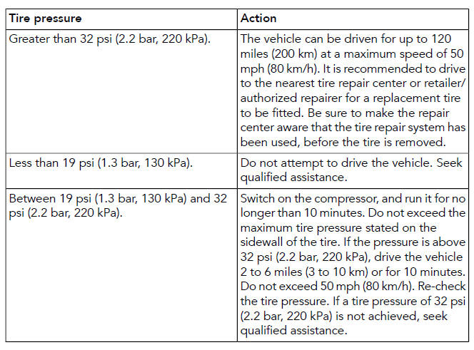
17. Check the repaired tire's pressure.
Refer to the table below.
READ NEXT:
 After using the tire repair system
When driving the vehicle, if vibrations,
abnormal steering, or noises are
experienced, reduce speed immediately.
Drive with extreme caution, at reduced
speed, to the first safe place to stop the
veh
Wheel changing safety
Make sure to read and fully understand
the following warnings. Failure to comply
with the safety instructions could result in
an accident, leading to serious injury or
death.
Note: If in any doubt reg
SEE MORE:
Front Row Seat Cushion - Vehicles With: Nas Specification
REMOVAL AND INSTALLATION
REMOVAL
CAUTION:
The front passenger seat heater mat and Restraints Occupant Classification
System Module (OCS) are
available only as a service kit. No attempt should be made to replace individual
components. Failure to follow
this instruction may result in personal injury
Front Door Impact Pressure Sensor
REMOVAL AND INSTALLATION
REMOVAL
WARNINGS:
To prevent accidental deployment, you must power down the Restraints
Control Module (RCM). Wait at
least 1 minute after you disconnect the startup battery ground cable before
you do any work on the
Supplementary Restraint System (SRS). If you do not
