
Land Rover Defender: Occupant sensing

Make sure to read and fully understand the relevant warnings before using any of the features in this section.

Crash statistics show that children are safest when properly restrained in a child restraint system. Children should be placed in an age and weight appropriate child restraint system and should be secured in a rear seating position.

Extreme hazard! Never place a rearward-facing child restraint on the front passenger seat. The infant could be seriously injured or killed if the air bag deploys.

For optimum safety, children under the age of 13 should travel in the rear of the vehicle at all times. Front passenger seat travel is not recommended. An inflating air bag could cause injury or death to children traveling in the front passenger seat.
The front outboard passenger seat is fitted with an occupancy sensor system that determines if:
- The seat is unoccupied.
- The seat is occupied by a person or object of low weight, or a child seat.
- The seat is occupied by a heavier person or object.
The system consists of:
- A weight sensing pressure pad fitted under the front passenger seat cushion. The sensor measures downward pressure and weight on the seat cushion.
- A control unit integrated into the pressure sensor.
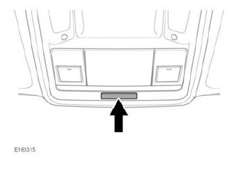
- An air bag status indicator lamp, mounted in the roof console.

Make sure the ignition is switched on when checking the operational status of the front passenger air bag.
Operational states
There are three operational states. The operational states are shown in the following table:
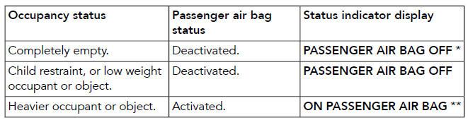
* If the status lamp shows that the air bag
is off with a seated adult in the front
passenger seat, contact a retailer/
authorized repairer immediately.
** Displays for 60 seconds, followed by
no display.
READ NEXT:
 Instrument panel overview
The instrument panel displays information,
warnings, and menu options to the driver.
The vehicle has one of the following
instrument panels:
Standard instrument panel.
Virtual instrument panel.
Information panel
The information panel displays information
and menu selection options. The
information panel can be configured to
meet personal preferences.
FUEL GAUGE
The fuel gauge displays the current fuel
tank le
SEE MORE:
Anti-Theft - Active - Diagnosis and Testing
DIAGNOSIS AND TESTING
PRINCIPLES OF OPERATION
Vehicle Immobilizer Control Module (VIM)
For a detailed description of the anti-theft - active operation, refer to the
relevant description and operation section of
the workshop manual. REFER to: Anti-Theft - Active (Anti-Theft - Active,
Description an
Front Lower Control Arm
REMOVAL AND INSTALLATION
SPECIAL TOOL(S)
204-506/1
Remover/Installer, Halfshaft
204-506/3
Remover/Installer, Halfshaft Screw Thread
204-506/5
Retainers, Halfshaft tools
204-598
Hydraulic Cylinder 10t
JLR-204-793A
Ball Joint Splitter
JLR-204-803
Splitter, Upper Arm
JLR-204-838
Ball joint spl
