Land Rover Defender: Hill Descent Control (HDC)
HILL DESCENT CONTROL (HDC)
Hill Descent Control (HDC) restricts the vehicle's speed to a set limit when traveling downhill.

Do not attempt a steep descent if HDC is inoperative or warning messages are displayed. Doing so could lead to loss of vehicle control, resulting in vehicle damage, personal injury, or death.

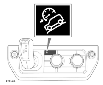
Press the button to select HDC. The instrument panel displays a confirmation message and illuminates the HDC information lamp to confirm HDC selection.
Note: HDC is automatically selected by some terrain response driving programs.
HDC remains selected for up to 6 hours after the vehicle's ignition is switched off.
Pressing the button a second time deselects HDC and selects All Terrain Progress Control (ATPC).
Pressing the button a third time deselects both systems.
If HDC is deselected while it is active, operation fades out, allowing the vehicle's speed to increase. The HDC information lamp extinguishes.

To adjust the vehicle's rate of descent:
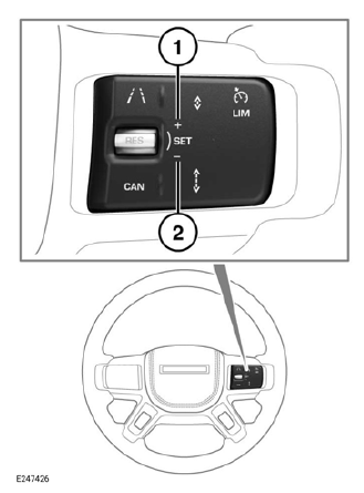
- Move the switch to the SET+ position to increase the vehicle's speed in increments of 0.6 mph (1 km/h). Move and hold the switch in the SET+ position for larger increases, up to the maximum permissible speed.
- Move the switch to the SET- position to decrease the vehicle's speed in increments of 0.6 mph (1 km/h). Move and hold the switch in the SETposition for larger increases, down to the minimum permissible speed.
The instrument panel displays the current set speed and the range of set speeds available.
Note: The maximum and minimum permissible speeds are dependent on the gear selected.
Note: The vehicle's speed only increases on a slope steep enough to increase momentum. Using the SET+ button may not increase the vehicle's speed on a gentle slope.
Note: A pulsation may be felt through the brake pedal if the brakes are used when HDC is active. HDC operation resumes when the brake pedal is released.
HILL DESCENT CONTROL (HDC) LIMITATIONS
Hill Descent Control (HDC) does not operate when Park (P) is selected.
HDC operation is suspended if the vehicle's speed exceeds 19 mph (30 km/h).
HDC operation disables if the vehicle's speed increases to between 19 mph (30 km/h) and 50 mph (80 km/h). In this instance, the instrument panel display turns gray and warning messages are displayed. The HDC information lamp also flashes.
If a fault is detected while HDC is active:
- HDC operation gradually fades out.
- The instrument panel displays a warning message.
- The HDC information lamp flashes.
GRADIENT RELEASE CONTROL (GRC)
Gradient Release Control (GRC) improves the vehicle's ability to smoothly pull away from a standstill when on an incline or decline. GRC achieves this by automatically controlling brake operation once the brake pedal is released. No driver intervention is required.
GRC operates when forward or reverse gears are selected.
GRC also operates if the brakes are applied while Hill Descent Control (HDC) is active.
GRC does not operate if the terrain response sand driving program is selected.
BRAKE TEMPERATURE
In extreme circumstances, prolonged use of the Hill Descent Control (HDC) system may cause excessive brake temperatures.
In this event, the instrument panel displays a warning message, indicating that the HDC system is temporarily unavailable.
HDC operation fades out and becomes temporarily inactive.
When the brake temperatures have returned to normal, the instrument panel warning message extinguishes and HDC operation resumes.

