Land Rover Defender: Enabling all terrain progress control (ATPC)

Make sure the relevant safety warnings have been read and understood before using All Terrain Progress Control (ATPC).
ATPC can be enabled when the vehicle is stationary or moving. When enabled, the system defaults to descent control mode.

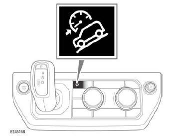
The ATPC button is located on the front control panel. The ATPC button also controls operation of the Hill Descent Control (HDC) system.
The button operates as follows:
- A first press of the button enables the HDC system.
- A second press of the button disables the HDC system and enables ATPC.
- A third press of the button disables ATPC.
 The
instrument panel displays
an information lamp, a speed
gauge, and a message to
confirm that ATPC has been
enabled.
The instrument panel also displays a message prompting the driver to select a set speed for the vehicle.
ATPC remains enabled for 6 hours after the vehicle's ignition has been switched off.
DESCENT CONTROL MODE

Make sure the relevant safety warnings have been read and understood before using All Terrain Progress Control (ATPC).
Descent control mode attempts to maintain a constant vehicle speed when descending a slope.
To enter descent control mode:
1. Carefully position the vehicle at the top of a slope.
2. With the vehicle stationary, press and hold the brake pedal.
3. Enable ATPC.
4. Select an appropriate terrain response program.
5. Select Drive (D).
6. Release the brake pedal.
ATPC takes control of the vehicle's speed during the descent. The selected terrain response program determines the vehicle's speed during the descent. The vehicle's speed can be reduced by moving the SET switch on the right side steering wheel controls downward.
ATPC suspends descent control mode operation if the accelerator pedal is pressed. Descent control mode resumes once the accelerator pedal is no longer being used.

