
Land Rover Defender: Driver Assistance Systems
PARKING AID
DRIVER ASSISTANCE DOMAIN CONTROLLER
REMOVAL AND INSTALLATION
GENERAL EQUIPMENT
.png)
REMOVAL
NOTES:
- This procedure contains some variation in the illustrations depending on the vehicle specification, but the essential information is always correct.
- This procedure contains illustrations showing certain components removed to provide extra clarity.
The following step(s) applies to: All vehicles
1. Disconnect the startup battery ground cable.
2.
- Release the 2 clips.
- Release the footwell lamp.
3.
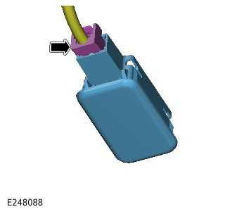
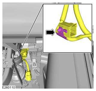
- Disconnect the electrical connector.
- Remove the footwell lamp.
4.
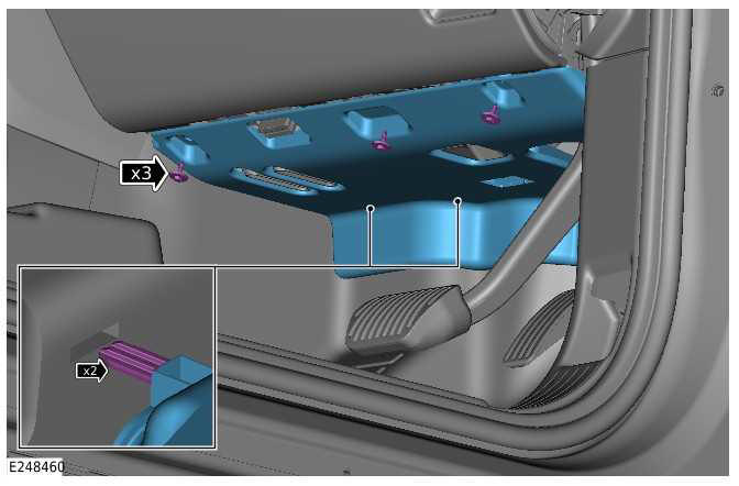
- Remove the 3 screws.
- Release the 2 clips.
- Remove the footwell trim panel.
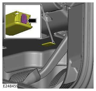
The following step(s) applies to: Right hand drive vehicles
5.
- Disconnect the electrical connector.
- Remove the 2 nuts.
- Remove the accelerator pedal assembly.
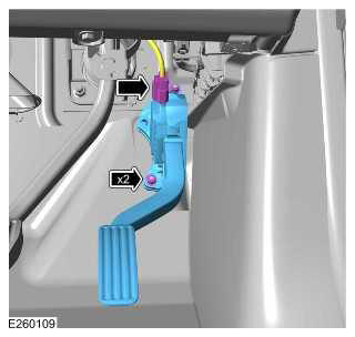
6.
Release the wiring harness clip.
The following step(s) applies to: All vehicles
7.
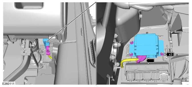
- Disconnect the electrical connector.
- Remove the 3 nuts.
- Remove the Driver Assistance Domain Controller (DADC).
INSTALLATION
The following step(s) applies to: All vehicles
1.
- Install the DADC.
- Install and tighten the 3 nuts.
Torque: 10Nm
- Connect the electrical connector to the DADC.
The following step(s) applies to: Right hand drive vehicles
2. Install the wiring harness clip to the brake pedal bracket.
3.
- Install the accelerator pedal assembly.
- Install and tighten the 2 nuts.
Torque: 10Nm
- Connect the electrical connector to the accelerator pedal assembly.
The following step(s) applies to: All vehicles
4.
- Install the footwell trim panel.
- Install and tighten the 3 screws.
5.
- Connect the electrical connector to the footwell lamp.
- Install the footwell lamp at the 2 clips.
6. Connect the startup battery ground cable.
7.
NOTE: This step is only required if a new component is installed.
- Use the Jaguar Land Rover (JLR) approved diagnostic equipment to
configure the new module.
General Equipment: Jaguar Land Rover approved diagnostic equipment
- Follow all on-screen instructions to complete this task.
READ NEXT:
 Climate Control System - General Information
SPECIFICATIONS
Climate Control
NOTE:
ROW Vehicles.
Climate Control
NOTE:
NAS Vehicles.
Climate Control
NOTE:
EU Vehicles.
Lubricants, Fluids, Sealers and Adhesives
CAUTION:
The HFO-1234yf and the R
Auxiliary Climate Control
DIAGNOSIS AND TESTING
PRINCIPLES OF OPERATION
For a detailed description of the auxiliary climate control system and
operation, refer to the relevant description and
operation section of the workshop
SEE MORE:
Exterior Lighting - Component Location, Overview
COMPONENT LOCATION
COMPONENT LOCATION - 1 OF 4 - FRONT LAMPS
NOTE:
Vehicle with 5 doors is shown, vehicle with 3 doors is similar.
Headlamp assembly (quantity 2)
Rain/light sensor
Image Processing Module (IPMA)
Door mirror - Side repeater lamp (quantity 2)
Front height sensor (quantity 2)
Fr
Air Suspension Manual Tight Tolerance Setting Mode
GENERAL PROCEDURES
ACTIVATION
NOTES:
If this procedure has been successful the instrument cluster will
emit 2 soft chimes 1 second after the
drivers door is closed. The instrument cluster will then emit 2 soft chimes
each time the drivers door is
closed to confirm that air suspension manual
