
Land Rover Defender: Wheel changing
Make sure to read and fully understand the following warnings. Failure to comply with the safety instructions could result in an accident, leading to serious injury or death.

Make sure the relevant safety warnings have been read and understood before changing a wheel.

Disconnect any trailer or caravan from the vehicle.

The standard vehicle jacking points should be used to raise the vehicle. Do not raise the vehicle by jacking under the fixed side steps, deployable side steps, or side tubes.

Only jack the vehicle using the jacking points described, or damage to the vehicle could occur.
Note: To allow easier access to the vehicle jacking points, it is recommended that the deployable side steps are in the stored position.
Note: Vehicles fitted with deployable side steps: Select off-road height before jacking the vehicle.
Before raising the vehicle:
1. Remove the required tools from the vehicle.
2. Remove the spare wheel.
3. Correctly position the wheel chocks.
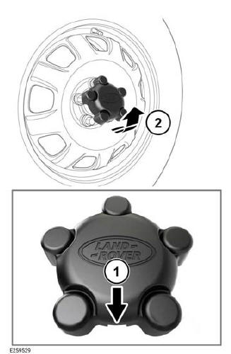
Vehicles with steel wheels have a hubcap.
To remove the hubcap:
- Insert a suitable tool into the slot on the hub cap.
- Carefully lever the hub cap off the lug nuts.
To change a wheel:
1. Use the lug wrench to loosen the lug nuts of the wheel to be replaced. Turn half a turn counter-clockwise.
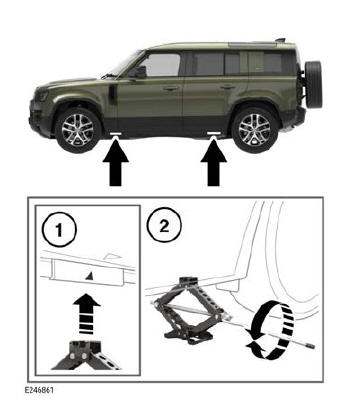
2. Locate the jack under the relevant jacking point (1).

Do not allow the jack to contact the sill at any other point, as damage may result.
3. Unfold the handle from the stored position on the jack. Fit the lug wrench to the end of the cranking handle.
4. Rotate the handle clockwise (2) to raise the jack, until the jack pin locates into the jacking point.
5. Raise the vehicle until the wheel is clear of the ground.

Avoid rapid, jerky actions. Rapid, jerky actions may cause the vehicle and jack to become unstable, which may result in an accident, leading to serious injury or death.
6. Remove the lug nuts. Place the lug nuts together where they cannot roll away.
7. Remove the wheel and place it to one side.

Do not lay the wheel on its face, as this may damage the finish.
8. Fit the spare wheel to the hub.
9. Refit the lug nuts. Lightly tighten the lug nuts. Make sure the wheel is making contact with the hub evenly.
10. Make sure the area under the vehicle is clear of obstructions. Lower the vehicle slowly and smoothly.
11. With all of the wheels on the ground and the jack removed, fully tighten the lug nuts. Tighten the lug nuts, in the sequence shown in the illustration, to the correct torque of 103 lb.ft (140 Nm).
Note: If it is not possible to torque the lug nuts when a wheel is replaced, set to the correct torque as soon as possible.
Check and adjust the tire pressure as soon as possible.
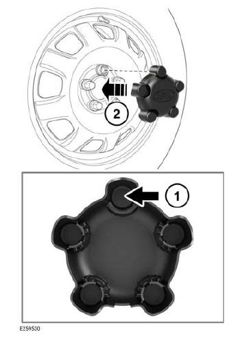

Make sure that the hubcap is correctly aligned to the locking lug nut.
To install the hubcap:
1. Align the hubcap to the locking lug nut.
2. Press the hubcap firmly into place.
READ NEXT:
 Recovery method
Make sure that vehicle recovery and/or
transportation is carried out by suitably
qualified personnel, and the vehicle is
secured correctly. Recovery and/or
transportation carried out by unqualified
p
Rear towing eye
The screw-in type rear recovery eyes are
designed for on-road recovery only. If
the screw-in type towing eyes are used
for any other purpose, it may result in
vehicle damage and can cause serious
inj
SEE MORE:
Windshield Moulding
REMOVAL AND INSTALLATION
REMOVAL
CAUTION:
Always protect paintwork and windows when removing exterior components.
NOTES:
This procedure contains some variation in the illustrations depending
on the vehicle specification, but the
essential information is always correct.
This procedure contains
Second Row Seat - 90
REMOVAL AND INSTALLATION
REMOVAL
WARNINGS:
To avoid accidental deployment, the Restraints Control Module (RCM)
backup power supply must be
depleted. Wait at least 2 minutes after disconnecting the startup battery
ground cable(s) before doing any
repair or adjustment to the Supplementary Rest
