
Land Rover Defender: Tire pressures
Make sure the relevant safety warnings have been read and understood before checking and adjusting the tire pressures.
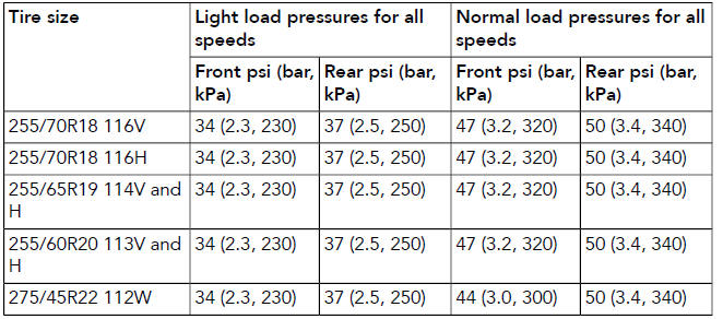
For vehicles with Tire Pressure Monitoring System (TPMS), inflate the tires to the advised pressures displayed in the instrument panel. The advised tire pressures are displayed in brackets in instrument panel.
Confirm that the TPMS loading setting is correct. If the advised tire pressures are not available in the instrument panel, or if TPMS is not fitted, when the tires are cold, inflate to the recommended cold tire pressures.
Tire inflation procedure

To avoid damaging the valves, do not apply excessive force or sideways pressure on the gauge and/or inflator.

To avoid damage to the TPMS valves, it is recommended not to use rigid tire inflation wands. Rigid tire inflation wands increase the risk of excess leverage and sideways pressure on the valve.
The following procedure should be used to adjust the tire pressures:
1. Remove the tire valve cap.
2. Firmly attach a tire pressure gauge and/or inflator to the valve.
3. Read the tire pressure from the gauge and add air, if required.
4. If air is added to the tire via a manual gauge, remove the gauge and reattach it before reading the pressure.
Failure to do so may result in an inaccurate reading.
5. Refit the valve cap.
For the latest available information on the tire pressures, visit: www.ownerinfo.landrover.com.
READ NEXT:
 Tire pressure label
The recommended tire pressures are listed
on a label located in the driver's door
opening.
These pressures provide optimum ride
and handling characteristics for all normal
operating conditions.
The
Replacement tires
Make sure the following warnings and
notices have been read and fully
understood. Failure to comply with the
safety instructions could result in damage
to the vehicle, or an accident, leading to
serio
Using winter tires
A dedicated winter tire often has a
lower speed rating than the original
equipment tire. Consequently, the
vehicle must be driven within the speed
limitation of the winter tire. Consult a
retailer/au
SEE MORE:
Secondary Bulkhead Left Panel
REMOVAL AND INSTALLATION
REMOVAL
NOTE:
This procedure contains some variation in the illustrations depending
on the vehicle specification, but the
essential information is always correct.
This procedure contains illustrations showing certain components
removed to provide extra clarity.
The
Windshield Moulding Carrier
REMOVAL AND INSTALLATION
REMOVAL
CAUTION:
Always protect paintwork and windows when removing exterior components.
NOTES:
This procedure contains some variation in the illustrations depending
on the vehicle specification, but the
essential information is always correct.
This procedure contains
