
Land Rover Defender: Tire markings
Land Rover Defender 2020-2026 Owner's Manual / Tires / Tire markings
Make sure the relevant safety warnings have been read and understood before replacing a tire.
All replacement tires must be the same specification as the original equipment tires, except for approved winter tires, off-road tires, and Professional Off-Road (POR) tires. If in doubt, consult a retailer/authorized repairer. Failing to comply with these rules can lead to accidents, potentially causing serious injury or death.
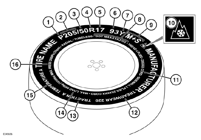
- P indicates that the tire is for passenger vehicle use. The index is not always shown.
- The width of the tire from sidewall edge to sidewall edge, given in mm.
- The aspect ratio, also known as the profile, gives the sidewall height as a percentage of the tread width. For example, if the tread width is 205 mm and the aspect ratio is 50, the sidewall height will be 102 mm.
- R indicates that the tire is of radial ply construction.
- The diameter of the wheel rim, given in inches.
- The load index for the tire. The load index specifies the maximum load the tire can carry at the speed indicated by the tire's speed rating. The index is not always shown.
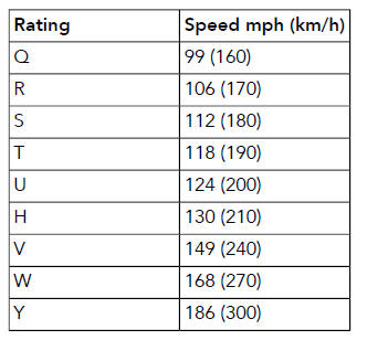
- The speed rating denotes the maximum speed at which the tire should be used for extended periods.
- U.S. DOT Tire Identification Number (TIN): The TIN begins with the letters DOT and indicates that the tire meets all federal standards. The next two numbers or letters are the plant code where the tire was manufactured. The last four numbers are the date of manufacture. For example, if the number is 3109, the tire was made in the 31st week of 2009. The other numbers are marketing codes used at the manufacturer's discretion. The information can be used to contact consumers if a tire defect requires a recall.
- M+S or M/S indicates that the tire has been designed with some capability for mud and snow.
- The winter tires symbol identifies dedicated winter tires.
- The number of plies in both the tread area and the sidewall area. The number of plies indicates how many layers of rubber-coated material make up the structure of the tire. Information is also provided on the type of materials used.
- Wear rate indicator: A tire rated at 400, e.g., lasts longer than a tire rated at 200.
- The traction rating grades a tire's
performance when stopping on a wet
road surface. The higher the grade,
the better the braking performance.
The grades, from highest to lowest, are: AA, A, B, and C.
- The maximum load which can be carried by the tire.
- Heat resistance grading: The tire's resistance to heat is grade A, B, or C, with A indicating the greatest resistance to heat. The grading is provided for a correctly inflated tire which is being used within its speed and loading limits.
- The maximum inflation pressure for the tire. The maximum inflation pressure should not be used for normal driving.
Note: Approved tires are generally identified by the brand mark J, LR, or J LR. Brand markings are specifically excluded for winter and POR tires.
SPEED RATINGS
READ NEXT:
 Tire care
Make sure the following warnings have
been read and fully understood before
driving the vehicle. Failure to do so may
result in an accident, leading to serious
injury or death.
Do not drive the vehic
Tire pressures
Make sure the relevant safety warnings
have been read and understood before
checking and adjusting the tire pressures.
For vehicles with Tire Pressure Monitoring
System (TPMS), inflate the tires to t
Tire pressure label
The recommended tire pressures are listed
on a label located in the driver's door
opening.
These pressures provide optimum ride
and handling characteristics for all normal
operating conditions.
The
SEE MORE:
Rain/Light Sensor
REMOVAL AND INSTALLATION
GENERAL EQUIPMENT
REMOVAL
CAUTIONS:
Make sure the ignition is OFF at all times during the replacement
procedure.
Care must be taken to avoid damaging the surrounding components.
After removal and installation of the rain/light sensor, wait 10
minutes before the cali
Matte Bonnet Decal
MATTE BONNET DECAL - PART NUMBER:
VPLEB0438
REMOVAL AND INSTALLATION
WARNING:
Accessories which are not correctly installed can be dangerous. Read the
instructions carefully prior to
installation. Comply with instructions at all times. If in doubt, contact your
nearest approved retailer.
CAUTIONS:
© 2010-2026 Copyright www.lrdefender.org
